

Vehicle body structure optimization method and system
An optimization method and body technology, applied in design optimization/simulation, special data processing applications, instruments, etc., can solve the problems of high chassis cost and poor commonality of parts, and achieve the effect of improving ride comfort, performance and versatility
- Summary
- Abstract
- Description
- Claims
- Application Information
AI Technical Summary
Problems solved by technology
Method used
Image

Examples
Embodiment Construction
[0061] In order to make the purpose, technical solutions and advantages of the embodiments of the present invention clearer, the technical solutions in the embodiments of the present invention will be clearly and completely described below in conjunction with the drawings in the embodiments of the present invention. Obviously, the described embodiments It is a part of embodiments of the present invention, but not all embodiments. Based on the embodiments of the present invention, all other embodiments obtained by persons of ordinary skill in the art without making creative efforts belong to the protection scope of the present invention.
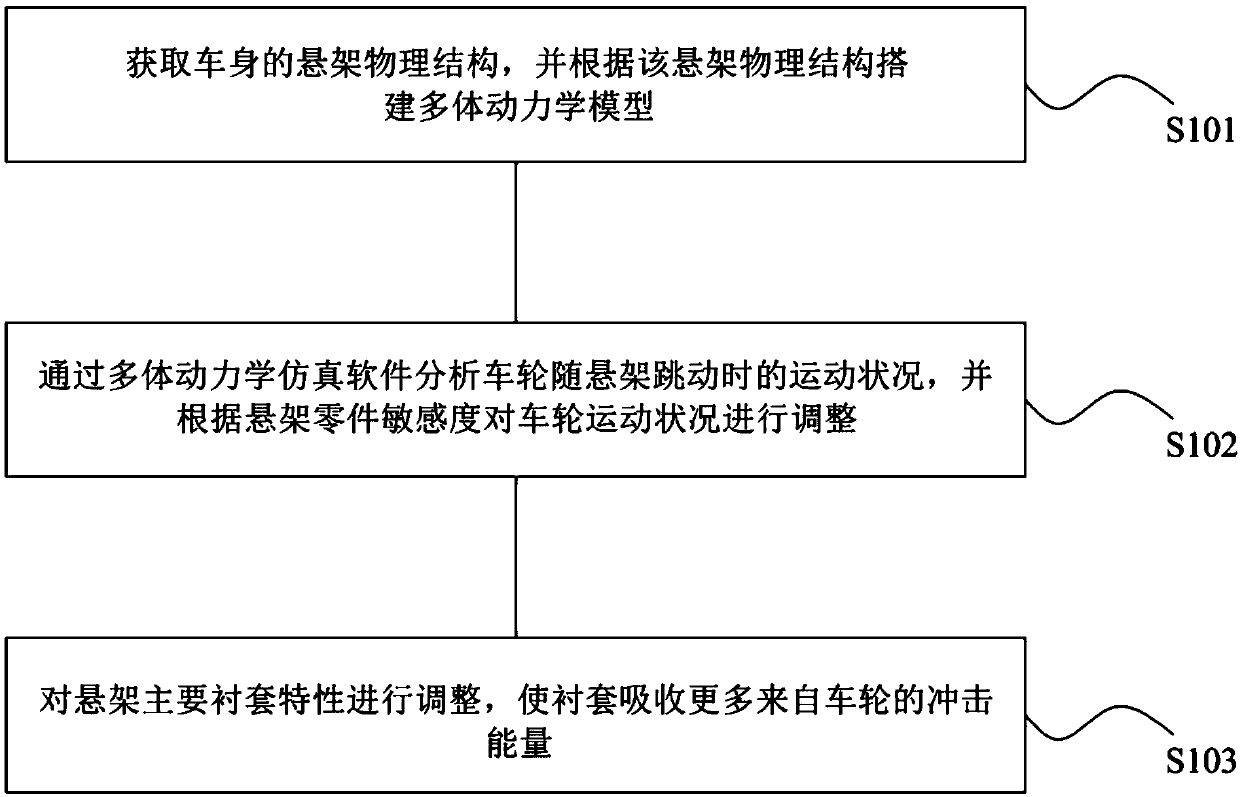
[0062] see figure 1 , a vehicle body structure optimization method proposed in the first embodiment of the present invention, including steps S101-S103.
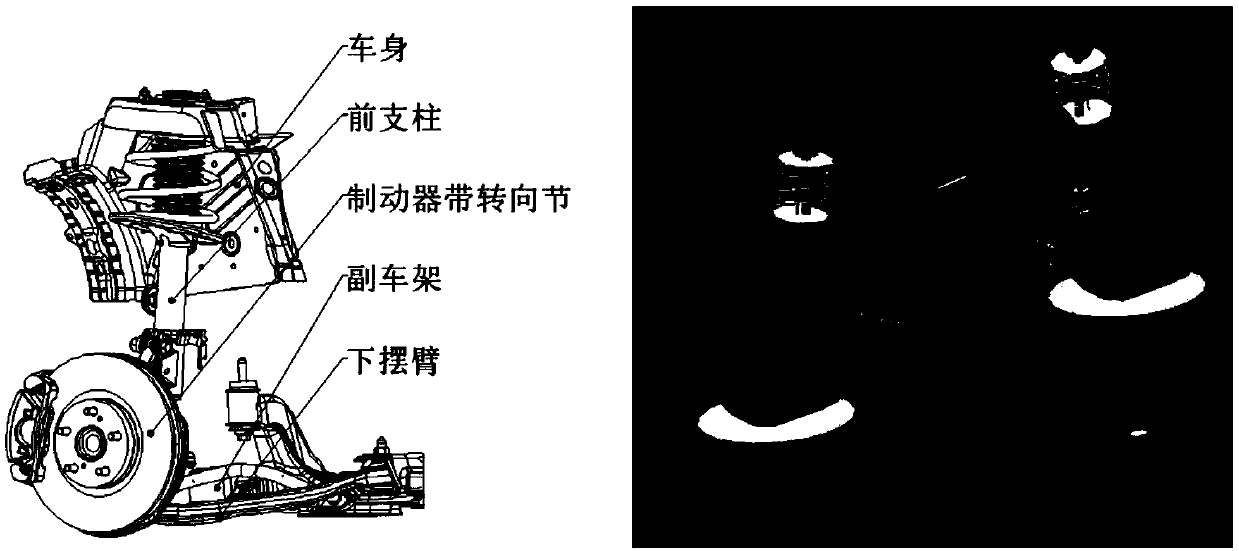
[0063]S101, obtaining the suspension physical structure of the vehicle body, and building a multi-body dynamics model according to the suspension physical structure;
[0064] Among them, ...
PUM
 Abstract
Description
Claims
Application Information