Boosting three-bridge-arm inverter and boosting adjustment method

A technology of three bridge arms and inverters, which is applied in the direction of converting AC power input to DC power output, output power conversion devices, electrical components, etc., which can solve the problem of serious heat generation of the down tube, reduce loss and reduce voltage ripple, the effect of improving system efficiency

Pending Publication Date: 2019-04-26
HARBIN UNIV OF SCI & TECH
View PDF0 Cites 2 Cited by
  • Summary
  • Abstract
  • Description
  • Claims
  • Application Information

AI Technical Summary

Problems solved by technology

[0004] attached figure 2 The displayed content is the commonly used full-bridge inverter topology. In a 380V system, the withstand voltage of the power tube is generally above 800V, and the lower tube of the long-used full-bridge inverter circuit also has the function of current continuous flow, often The heat generation of the down tube is serious, and in the figure 1 When the converter 102 is non-isolated, leakage current will be generated when the power supply load 101 is a solar panel, and a discharge circuit will be generated when the electric equipment is shared with the ground

Method used


Image

  • Boosting three-bridge-arm inverter and boosting adjustment method
  • Boosting three-bridge-arm inverter and boosting adjustment method
  • Boosting three-bridge-arm inverter and boosting adjustment method

Examples


Embodiment 1

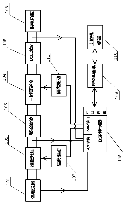
[0028] A step-up three-leg inverter, which consists of: a power supply equipment module, the power supply equipment module is connected to a push-pull boost module, the push-pull boost module is connected to a rectification and filtering module, and the The rectifier filter module is connected to the three-arm inverter bridge module, the three-arm inverter bridge module is connected to the LCL filter module, and the LCL filter module is connected to the power supply load;

[0029] The power supply equipment module, the push-pull boost module, and the LCL filter module output signals to the A / D conversion end of the DSP main controller respectively, and the PWM output port of the DSP main controller is connected to the isolation drive module respectively. A. The isolated drive module B is connected, the isolated drive module A is connected to the push-pull boost module, the isolated drive module B is connected to the three-arm inverter bridge module, and the DSP The main contro...

Embodiment 2

[0041] According to the step-up three-leg inverter described in Embodiment 1, the isolated drive module includes a signal conversion module, and the signal conversion module is respectively connected to the drive module, the voltage rectification and filtering module, and the DSP main controller. The voltage rectification and filtering module described above feeds back the rectified voltage to the IC control module through the coupling of electrically isolated signals, and the IC control module is connected to the power conversion circuit module, and the power conversion circuit module is connected to the voltage Rectifier filter module connection.

[0042] Figure 8 A block diagram for the isolated drive, including:

[0043] Main control IC module 301: controls the output of PWM through IC, and performs chip enable, overvoltage, undervoltage, overcurrent and other controls.

[0044] The power conversion module 302: controls the power part through the output of PWM, and exci...

Embodiment 3

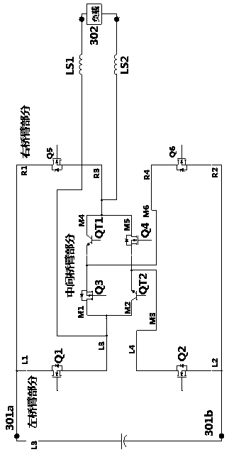
[0050] According to the step-up three-leg inverter described in Embodiment 1 or 2, the three-leg inverter bridge module includes a left bridge arm, an intermediate bridge arm and a right bridge arm, and the left bridge arm includes a MOS tube Q1, MOS tube Q2, the middle bridge arm includes IGBT tube QT1, IGBT tube QT2, MOS tube Q3, MOS tube Q4, the right bridge arm includes MOS tube Q5, MOS tube Q6; the pin L1 of the left bridge arm and the positive input of the capacitor Terminal connection, the L2 pin of the left bridge arm is connected to the negative input terminal of the capacitor, the L3 pin of the left bridge arm is connected to the M1 and M2 of the middle bridge arm, the L4 pin of the left bridge arm is connected to the M3 of the middle bridge arm, The pin R1 of the right bridge arm is connected to the positive input terminal of the capacitor, the R2 pin of the right bridge arm is connected to the negative input terminal of the capacitor, the R3 pin of the right bridge ...


PUM


Abstract

The invention discloses a boosting three-bridge-arm inverter and a boosting adjustment method. A power pipe in a 380-V system usually resists to the voltage of 800 V or above generally, a lower pipe of a full bridge inversion circuit is often high in heat emitting amount, and the content of harmonic waves in a power grid is also very high. The boosting three-bridge-arm inverter comprises a power supply equipment module (101) which is connected with a push-pull boosting module (102), the push-pull boosting module is connected with a rectifying filter module (103) which is connected with a three-bridge-arm inversion bridge module (104), and the three-bridge-arm inversion bridge module is connected with an LCL filter module (105); and the power supply equipment module, the push-pull boostingmodule and the LCL filter module output signals to the A / D conversion end of a DSP main controller (108), and a PWM output port of the DSP main controller is connected with an isolation driving moduleA (107) and an isolation driving module B (111). The boosting adjustment method is applied to the boosting three-bridge-arm inverter.

Description

Technical field: [0001] The invention relates to a step-up three-bridge arm inverter and a step-up regulating method. Background technique: [0002] The inverter is a device that converts direct current into alternating current. It is often used in active filters, reactive power compensators, and high-voltage frequency conversion devices. Generally, the withstand voltage of the power tube is relatively high, usually in a 380V system. The withstand voltage is generally above 800V, and the lower tube of the long-term used full-bridge inverter circuit also has the function of current continuous flow, often the heat generated by the lower tube is serious, and when the system is connected to the power grid, the full-bridge inverter circuit and The grid exchanges energy, which increases the content of harmonics in the grid. [0003] Therefore, how to provide an inverter circuit topology, reduce the cost of the circuit, improve the conversion efficiency and reduce the withstand vo...

Claims


Application Information

Patent Timeline
Patent Type & Authority Applications(China)
IPC IPC(8): H02M7/537H02M1/12
CPCH02M7/537H02M1/126
Inventor 张春博张显友刘骥董丽敏王守明魏洪达
Owner HARBIN UNIV OF SCI & TECH
Why Eureka
Try Eureka