Optical fiber macro bending online monitoring system and method

A monitoring system and macro-bending technology, which is applied in the field of optical fiber macro-bending online monitoring system, can solve the problems of high total power, small proportion of optical power, and inability to accurately judge the link, so as to reduce the misjudgment rate and improve accuracy Effect

Active Publication Date: 2021-09-28
SOUTHEAST UNIV
View PDF16 Cites 0 Cited by
  • Summary
  • Abstract
  • Description
  • Claims
  • Application Information

AI Technical Summary

Problems solved by technology

However, the total transmission power of NG-PON2 is large, the proportion of optical power leaked by macrobending eavesdropping is very small, and the OPP will increase significantly compared with the current standard passive optical network. These unfavorable factors will make the simple optical power detection technology unable to accurately judge Whether there is a macrobending eavesdropping event on the link

Method used


Image

  • Optical fiber macro bending online monitoring system and method
  • Optical fiber macro bending online monitoring system and method
  • Optical fiber macro bending online monitoring system and method

Examples


Embodiment 1

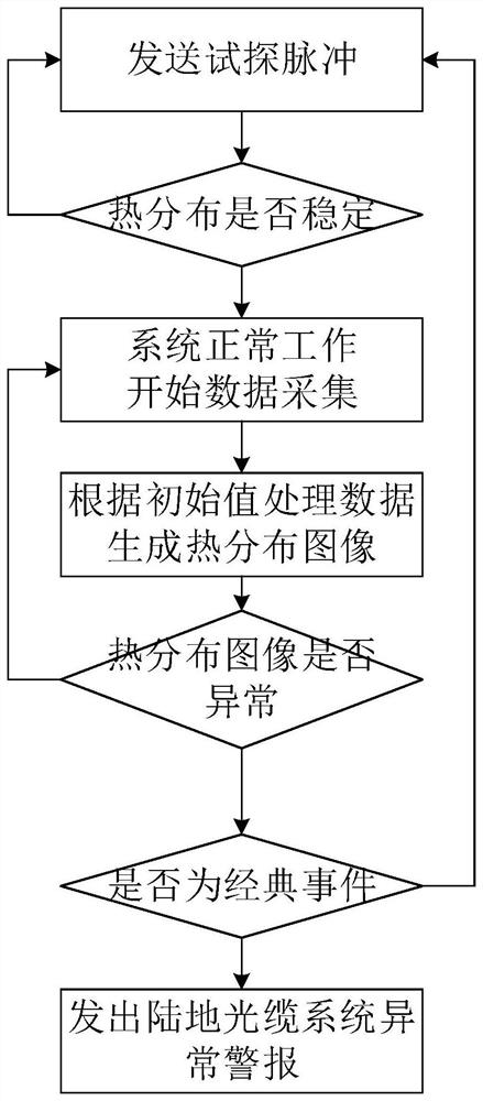
[0045] The terrestrial optical cable links are usually buried on the shallow surface and are easily affected by changes in external temperature (direct sunlight, heat transfer, etc.). adiabatic environment. The fiber optic cable can be filled with thermal insulation material to ensure that the optical fiber in the cable link is in a constant temperature and humidity environment even in complex situations.

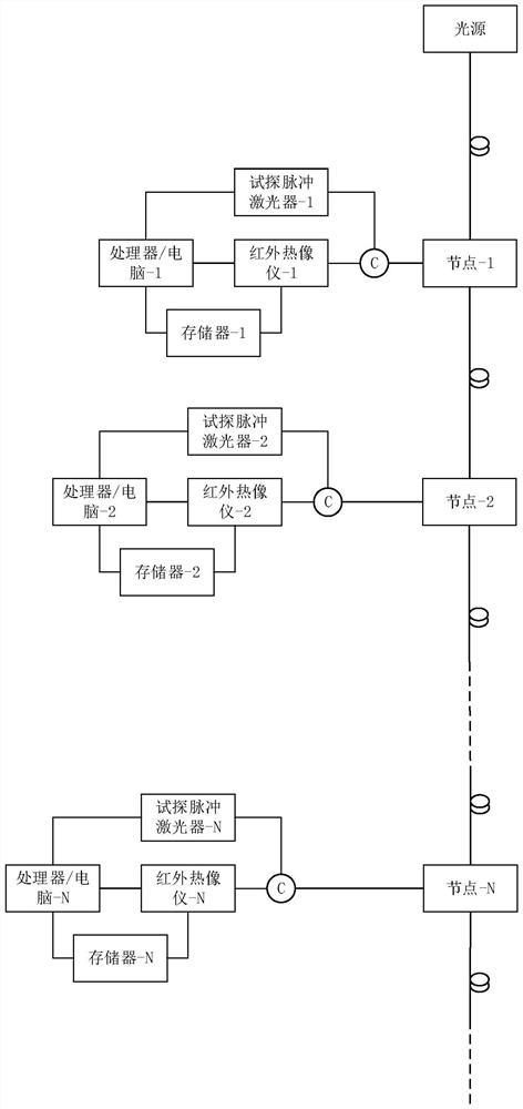
[0046] Place infrared thermal imaging cameras, memory, processors, test pulse lasers and other equipment at the relay station of the terrestrial optical cable link. In the system initialization stage, firstly, a test pulse laser is used to send a test pulse, and the infrared thermal imaging camera continuously collects and observes the thermal distribution data of the fiber end face. When the thermal distribution becomes stable, the data is stored. The initial value of the system between the previous nodes, which is used as the reference basis for system correction when cl...

Embodiment 2

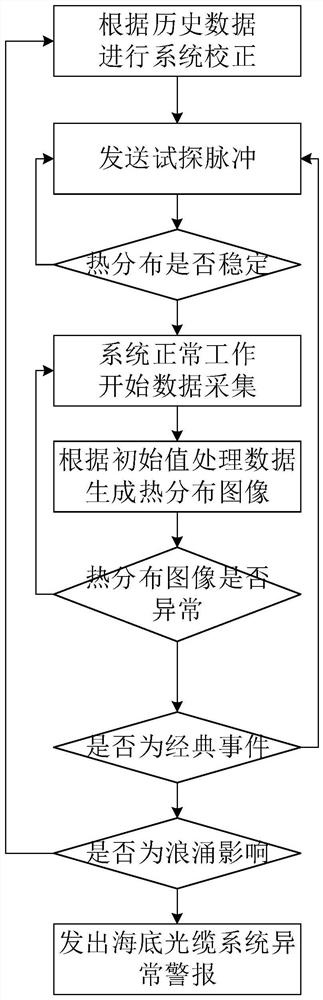
[0050] The submarine optical cable link is laid on the seabed, and the ambient temperature usually remains constant, so there is no need to fill the cable with insulating material, but the nodes of the submarine optical cable are usually included in the optical cable, so it is judged by monitoring the thermal distribution of the optical fiber end face whether there is In the case of macrobending eavesdropping, it is first necessary to miniaturize the thermal imaging camera so that devices such as thermal imaging cameras can be integrated in the submarine optical cable link system.

[0051] The observation process is basically the same as that of the terrestrial optical cable system. The difference is that some classic events similar to disturbances will occur in the submarine optical cable system. After a period of time, the disturbance can disappear and the system will recover itself. For example, submarine surges and wave fluctuations will bring vibrations to submarine optica...


PUM


Abstract

The invention discloses an on-line monitoring system for optical fiber macro bending, which comprises an infrared thermal imager, a processor and a display. The invention also discloses an online monitoring method for optical fiber macro-bending, which includes the following steps: step 1, using an infrared thermal imager to collect data on the thermal distribution change of the fiber end face of each optical link node; step 2, using a processor to collect Real-time processing of the data to obtain the thermal distribution image; step 3, according to the ordinate value z(x,y) of the thermal distribution image obtained in step 2 m , to determine whether there is a macrobending eavesdropping event in the link. This technical solution can effectively improve the accuracy of monitoring and reduce the misjudgment rate of illegal wiretapping by macrobending.

Description

technical field [0001] The invention relates to an on-line monitoring system and method for optical fiber macro bending. Background technique [0002] The next-generation passive optical network (NextGenerate Passive Optical Network, NG-PON2) based on the standard passive optical network system and compatible with the optical power distribution network has become a The next development goal of passive optical network. The multi-wavelength characteristics of NG-PON2 in the uplink and downlink will inevitably lead to the characteristics of large transmission power on the optical fiber link, and will also cause optical link damage such as Raman nonlinearity, dispersion, and crosstalk between channels on the link. (Optical Path Penalties, OPP). [0003] In the standard passive optical network system, there is a means of eavesdropping on optical signals by macro-bending a section of optical fiber and coupling out a small amount of fiber core optical energy (1% of the current op...

Claims


Application Information

Patent Timeline
Patent Type & Authority Patents(China)
IPC IPC(8): H04B10/079H04B10/85G01J5/00
CPCG01J5/0096G01J2005/0077H04B10/0795H04B10/85
Inventor 孙小菡叶晓凯戈志群樊鹤红郭浩刘朋朋李超张志选李双喜施泽楠
Owner SOUTHEAST UNIV
Why Eureka
Try Eureka