
Vehicle stability control system based on active intervention steering system

A stability control and steering system technology, applied in the direction of control devices, vehicle components, driver input parameters, etc., can solve the problems of limited intervention range, yaw effect cannot be completely eliminated, and limited degree of rear wheel intervention. To achieve the effect of ensuring vehicle stability and strengthening the stability control function

Active Publication Date: 2019-04-30
SAIC GENERAL MOTORS +1
View PDF7 Cites 16 Cited by
  • Summary
  • Abstract
  • Description
  • Claims
  • Application Information

AI Technical Summary

Problems solved by technology

[0005] The above stability control systems all have the ability to control or intervene in vehicle stability directly by adjusting the braking force of the wheels. However, due to the limitation of the mechanical characteristics of the tire phase plane, the range of intervention that can be achieved is still limited.
In addition, the rear wheel is responsible for the lateral support of the rear axle. The lateral force decreases with the increase of the slip rate, which determines the extent to which the rear wheel can be intervened. Otherwise, it is easy to cause the rear axle to become unstable.
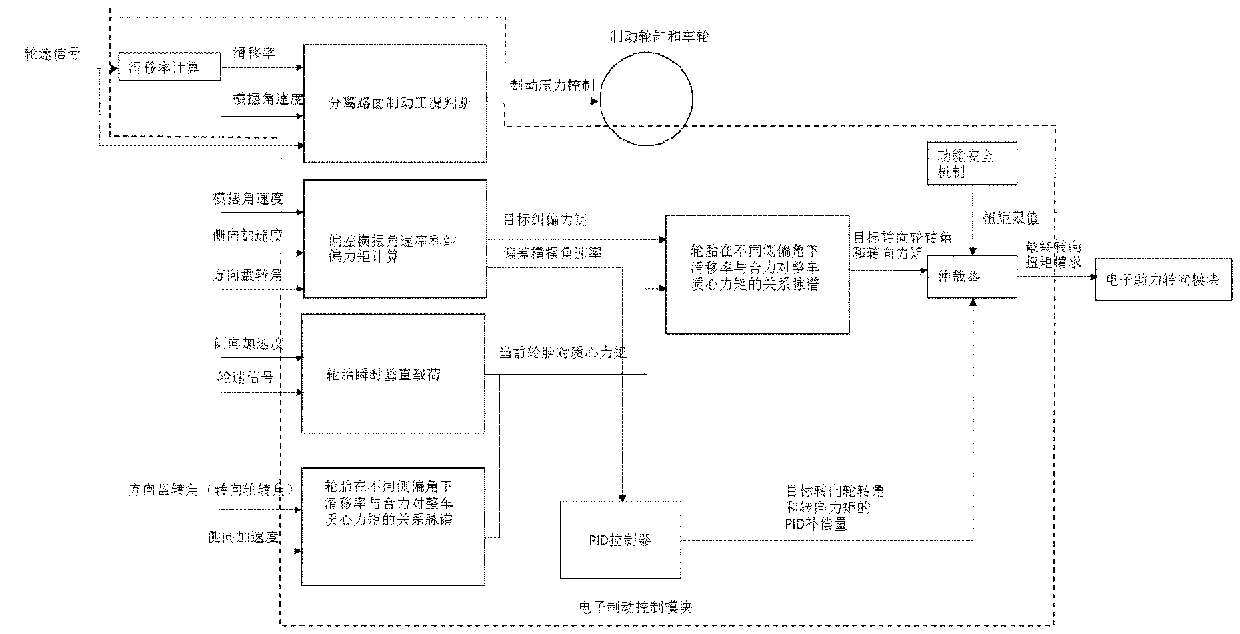
In the case of braking on separated roads, in order to ensure deceleration, the braking force on the high-attached side must be higher than that on the low-attached side, so the effect of yaw cannot be completely eliminated.

Method used


Image

  • Vehicle stability control system based on active intervention steering system
  • Vehicle stability control system based on active intervention steering system
  • Vehicle stability control system based on active intervention steering system

Examples


Embodiment Construction

[0055] Introduced below are some of the various embodiments of the invention, intended to provide a basic understanding of the invention. It is not intended to identify key or critical elements of the invention or to delineate the scope of protection.

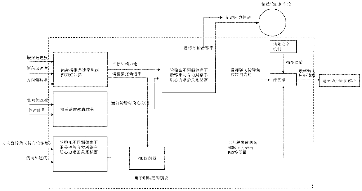
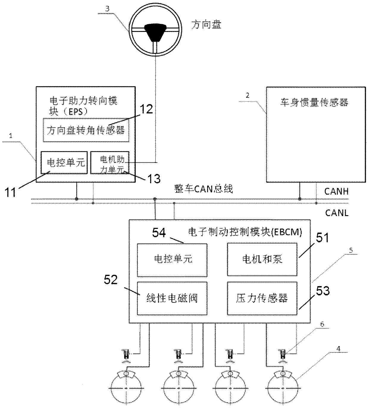
[0056] figure 1 It is a whole vehicle structure diagram of the stability control system that actively intervenes in the torque steering steering wheel operation of the steering system according to the present invention.

[0057] Refer below figure 1 , to illustrate the vehicle stability control system of the present invention that actively intervenes in the torque vectoring steering wheel operation of the steering system.

[0058] The vehicle stability control system of the present invention mainly includes: electronic power steering control module (EPS) 1 , vehicle body inertia sensor 2 , steering wheel 3 , brake wheel cylinder 4 , electronic brake control module (EBCM) 5 and wheel speed sensor 6 .

[0059] The electronic p...


PUM


Abstract

The invention relates to a vehicle stability control system based on an active intervention steering system, which is characterized by at least comprising: an electronic assistance steering module used for receiving a torque request instruction from an electronic brake control module and outputting torque for intervening with the positions of a turning wheel and a steering wheel by torque; the electronic brake control module configured to determine the running state of a vehicle according to the hydraulic pressure applied by the driver through the brake pedal, the wheel working state input through wheel speed sensors, and the vehicle actual acceleration and yaw rate signals input by vehicle inertia sensors and calculate the stability deviation of the current vehicle control state from theideal control state and the turning wheel rotating angle required to compensate for the stability deviation according to the brake back pressure applied by the driver, and obtain the assist torque value to be provided for achieving the target turning wheel rotating angle and send the same to the electronic assistance steering module.

Description

technical field [0001] The present invention relates to vehicle control technology, and more specifically relates to the addition of active steering system torque control on the basis of traditional stability control by adjusting brake pressure to change the angle of the steering wheel so as to generate additional yaw moment to strengthen the stability control effect vehicle stability control system. Background technique [0002] The existing road vehicle stability control systems mainly involve the following two categories: [0003] 1. Anti-lock brakes (ABS), this type of system collects wheel speed signals to estimate the vehicle's wheel running state, including wheel speed, wheel acceleration (deceleration), and slip rate. The ABS system regulates the pressure of each wheel cylinder by turning on and off the solenoid valve to achieve the purpose of preventing locking and controlling the stability of the vehicle body. The typical working condition is braking on separate...

Claims


Application Information

Patent Timeline
IPC IPC(8): B60W30/02B60W30/045B60W10/18B60W10/20
CPCB60W10/18B60W10/20B60W30/025B60W30/045B60W2520/125B60W2520/28B60W2540/00B60W2540/18B60W2710/18B60W2710/202
Inventor 夏天乐美祺赵向东朱玙熹杨洪福
Owner SAIC GENERAL MOTORS
Learn More