Adaptive adjusting method for transmitting power of induction log tool

A self-adaptive adjustment and induction logging technology, used in surveying, earth-moving drilling, wellbore/well components, etc., to achieve the effect of simple circuit design and optimized circuit structure

Active Publication Date: 2019-04-30
UNIV OF ELECTRONICS SCI & TECH OF CHINA
View PDF17 Cites 2 Cited by
  • Summary
  • Abstract
  • Description
  • Claims
  • Application Information

AI Technical Summary

Problems solved by technology

[0005] The purpose of the present invention is to propose a self-adaptive adjustment method for the transmission power of the induction logging tool in view of the deficiencies in the self-adaptive setting of the transmission power of the traditional logging tool

Method used


Image

  • Adaptive adjusting method for transmitting power of induction log tool
  • Adaptive adjusting method for transmitting power of induction log tool
  • Adaptive adjusting method for transmitting power of induction log tool

Examples


Embodiment 1

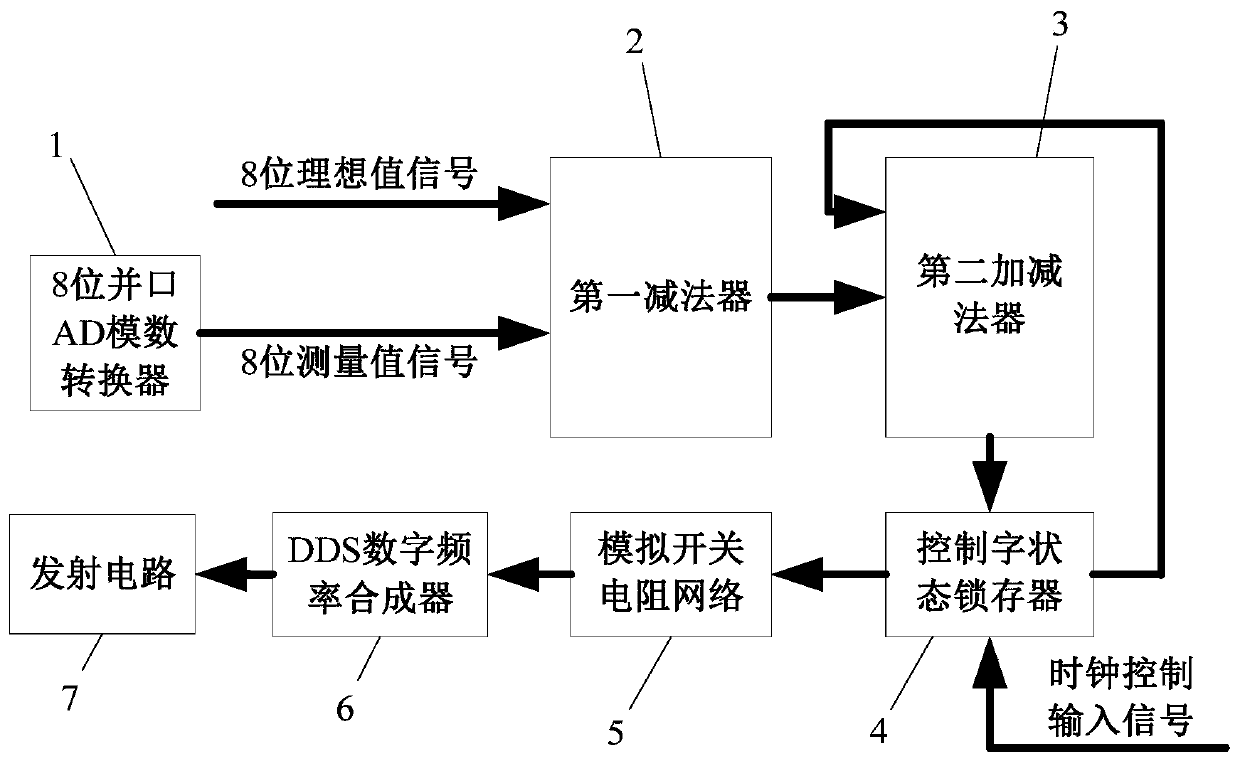
[0045] An embodiment of the present invention provides an adaptive adjustment device for the transmission power of an induction logging tool, such as figure 1 As shown, it includes an 8-bit parallel port AD analog-to-digital converter 1 , a first subtractor 2 , a second adder-subtractor 3 , a control word status latch 4 , an analog switch resistor network 5 and a DDS digital frequency synthesizer 6 .

[0046] The input terminal of the first subtractor 2 inputs 8 ideal value signals and the 8 measured value signals produced by the 8-bit parallel port AD analog-to-digital converter 1 respectively, and its output terminal is connected with the input terminal of the second adder-subtractor 3; The output end of the second adder-subtractor 3 is connected with the input end of the control word state latch 4; the output end of the control word state latch 4 is respectively connected with the second adder-subtractor 3 and the analog switch resistance network 5, And its control port con...

Embodiment 2

[0098] An embodiment of the present invention provides a method for adaptively adjusting the transmission power of an induction logging tool, such as Figure 9 As shown, the following steps S1-S10 are included:

[0099] S1. Conditioning, amplifying and filtering the signal output from the receiving coil of the induction logging tool, collecting the conditioning, amplified and filtered measurement signal through an 8-bit parallel port AD analog-to-digital converter, and converting it into an 8-bit measured value signal and inputting it into the first subtraction device.

[0100] The conditioning, amplifying and filtering circuit for conditioning, amplifying and filtering the output signal of the receiving coil is provided by the induction logging instrument itself. In the embodiment of the present invention, only the measurement signal needs to be introduced.

[0101] S2. In the first subtractor, the set 8-bit ideal value signal is used as the minuend, and the 8-bit measuremen...


PUM


Abstract

The invention discloses an adaptive adjusting method for transmitting power of an induction log tool. Configuration software or flash programming is not needed, and automatic adjustment is completelyrealized by a hardware circuit. According to the adaptive adjusting method disclosed by the invention, the transmitting power is automatically calculated and adjusted according to a signal acquired byan AD (Analog / Digital) converter, the final signal received by the induction log tool is ensured to be always positioned in an optimum state, the received signal is not too large so as not to be saturated, the signal is not too small so as not to cause insufficient measurement accuracy, and finally the effects of reducing partial power consumption of the system, reducing the manual step-up errorand improving the measurement accuracy and measurement efficiency are achieved. Meanwhile, since the design of a full hardware circuit is adopted for adjustment, program software participation is notneeded, and the reliability of the system is greatly improved.

Description

technical field [0001] The invention belongs to the technical field of transmission power automatic control, and in particular relates to the design of a self-adaptive adjustment method for the transmission power of an induction logging tool. Background technique [0002] With the rapid development of induction logging technology, most of the instrument systems in the field of well logging currently configure the transmission power artificially through the host computer interface in advance, or realize the transmission power by manually calculating the setting parameters many times during the measurement process. Configuration. After setting the transmission power, the instrument always measures according to the fixed transmission power, which inevitably has some disadvantages. If the transmission power is set too high in advance, there will be waste of transmission power, increased power consumption, low efficiency, and also It may cause the receiving circuit signal to be ...

Claims


Application Information

Patent Timeline
Patent Type & Authority Applications(China)
IPC IPC(8): E21B47/00E21B47/12
CPCE21B47/00E21B47/12
Inventor 管国云聂在平孙向阳
Owner UNIV OF ELECTRONICS SCI & TECH OF CHINA
Why Eureka
Try Eureka