Planetary gear train advantageously used in a servo motor system, method and servo motor system using the planetary gear train

A planetary gear train, servo motor technology, applied in the direction of elements with teeth, servo motor components, gear transmissions, etc., can solve problems such as not considering longer approach stages

Active Publication Date: 2022-04-22
BERNARD CONTROLS
View PDF7 Cites 0 Cited by
  • Summary
  • Abstract
  • Description
  • Claims
  • Application Information

AI Technical Summary

Problems solved by technology

However, in known manually controlled flywheel servomotor systems, the manual control mechanism of the valve is only designed to function for the short high force phase without regard to the longer approach phase

Method used


Image

  • Planetary gear train advantageously used in a servo motor system, method and servo motor system using the planetary gear train
  • Planetary gear train advantageously used in a servo motor system, method and servo motor system using the planetary gear train
  • Planetary gear train advantageously used in a servo motor system, method and servo motor system using the planetary gear train

Examples


Embodiment Construction

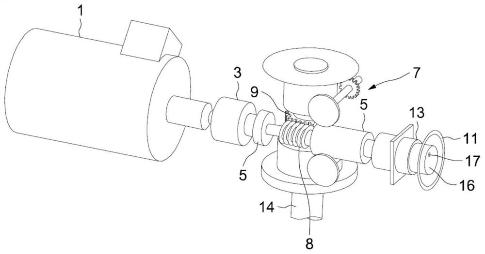
[0023] As a non-limiting example, the invention is described below as it applies to applications such as figure 1 The multi-turn servo motor system shown.

[0024] According to the synaptic block diagram of the figure, the system includes a motor 1, a planetary gear train 3, a beam force limiter 5 and a reducer 7 installed in series, which includes a worm 8 and a gear 9 driven by a screw 8 and connected to An output shaft 14 is fixed for rotation together, for driving an actuator member (such as a rotating member for closing and opening a valve of a pipe). The figure further shows a flywheel 11 for a manually actuated actuator and a clutch system 13 mounted in series with the worm 8 and a planetary gear train 16 provided with a control member 17 according to the invention.

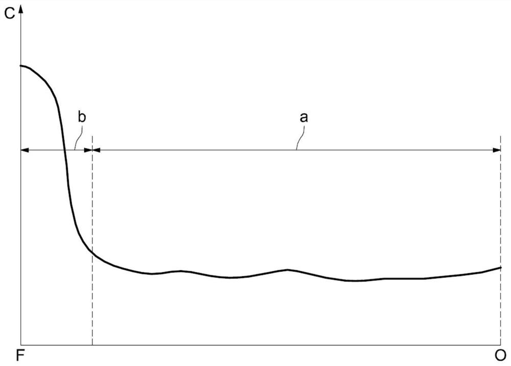
[0025] figure 2 The characteristic curve of the torque C of the moving actuator member of the valve is shown as a function of the travel of the member between an open position O on the right side of its...


PUM


Abstract

The invention relates to a planetary gear train advantageously used in a servomotor system, said planetary gear train of the type comprising a servomotor system positioned in a housing (18), a planetary gear carrying a plurality of planetary gears (26) frame (24), ring gear (28) and sun gear (30). Said planetary gear train is characterized in that it comprises means (40) for varying said input and output speed ratios, said means being actuatable from outside said housing (18). The invention can be used in a servo motor system.

Description

technical field [0001] The present invention relates to a planetary gear train advantageously used in a servo motor system, this type of planetary gear train comprises a servo motor system, a planet carrier, a ring gear and a sun gear housed in a housing between an input shaft and an output shaft Gears, and in particular control methods for valve and servo motor systems using such planetary gear trains and equipped with flywheel manual control mechanisms. Background technique [0002] It is known that the force required to close a valve is not constant, and in figure 2 The manner shown changes based on the travel of the moving member. During the longer approach phase of the moving member, i.e. until the sealing seat of the valve is reached, the force required is relatively constant and low, and only increases substantially during the brief tightening phase until the valve is closed, which duration is usually short 10% of the total travel time. However, in known manually c...

Claims


Application Information

Patent Timeline
Patent Type & Authority Patents(China)
IPC IPC(8): F16H37/04F16K31/04F16K31/53
CPCF16H37/041F16K31/043F16K31/535F16H3/54F16K31/055F16H2048/305F16H2200/0034F16H2200/2005F16H3/002F16H61/686F16H3/44F16H59/42F16H59/40H02K7/116F16H3/72F16K31/05F15B13/0406F15B13/0885F15B15/202F16H3/62
Inventor 艾蒂安·伯纳德雷米·勒潘
Owner BERNARD CONTROLS
Why Eureka
Try Eureka