Lifting type multifunctional steel pipe spraying equipment

A spraying equipment and multi-functional technology, applied in the field of lift-type multi-functional steel pipe spraying equipment, can solve the problems affecting the efficiency and quality of spraying, the size of the fixture is single, and the thickness of the paint film is not easy to control, etc. The effect of high production, high work efficiency and convenient high-speed production in large quantities

Inactive Publication Date: 2019-05-03
甘肃三色科技涂装工程有限公司
View PDF5 Cites 14 Cited by
  • Summary
  • Abstract
  • Description
  • Claims
  • Application Information

AI Technical Summary

Problems solved by technology

[0002] At present, the existing anti-rust spraying on the outer surface of the steel pipe mainly uses the paint pump to pass through the multiple paint spray holes in the ring pipe to spray directly on the surface of the steel pipe in all directions, so that the surface of the steel pipe can be sprayed and painted at a high speed without leakage. Paint phenomenon, and then use a number of paint brushes to evenly remove the excess paint, so that the excess paint flows back into the paint tank for automatic cycle spraying; the paint recovery rate of this spraying method is low, and the thickness of the paint film is difficult to control. The coating takes a long time to cure, and usually requires special drying furnace equipment, which takes up a lot of space
[0003] In the traditional technology, in the steel pipe spraying process, it is necessary to spray paint on the surface of the steel pipe, and the spraying needs to fix the sprayed parts. The current spraying fixtures often only have fixed functions, and the function is single, which greatly affects the efficiency and efficiency of spraying. quality, and the current fixtures are one size fits all and have poor applicability

Method used


Image

  • Lifting type multifunctional steel pipe spraying equipment
  • Lifting type multifunctional steel pipe spraying equipment
  • Lifting type multifunctional steel pipe spraying equipment

Examples


Embodiment

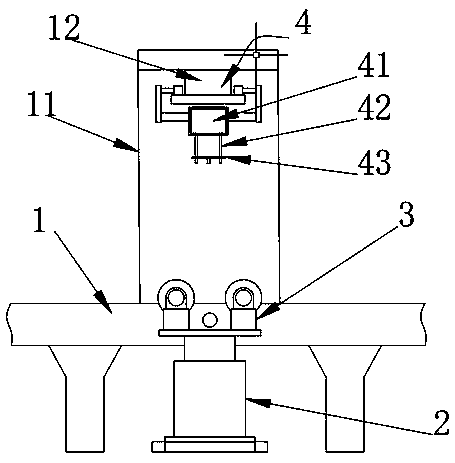
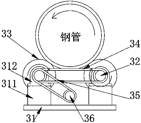
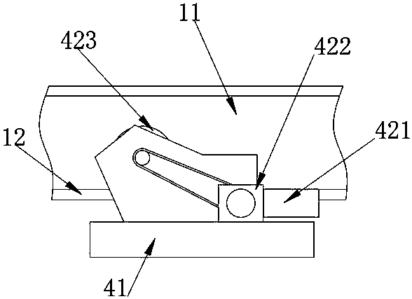
[0027] see Figure 1-3 , the present invention provides a technical solution: a lift-type multifunctional steel pipe spraying equipment, including a frame 1, a lifting assembly 2, a lifting roller set 3 and a spraying assembly 4, the lifting assembly 2 is installed on the support surface and Located on the inner side of the frame 1, and the output end of the lifting component 2 is equipped with a lifting roller group 3, the gantry frame 11 is fixed on the frame 1, the bottom of the gantry frame 11 is welded with a guide rail 12, and the spraying component 4 is connected to the guide rail by transmission 12, and the spraying assembly 4 is located above the lifting roller set 3.

[0028] In this embodiment, the lifting assembly 2 is installed on the support surface and is located inside the frame 1, and the output end of the lifting assembly 2 is equipped with a lifting roller set 3, and the steel pipe is transported laterally on the frame 1 through a transmission device , when...


PUM


Abstract

The invention belongs to the technical field of steel pipe spraying machining, and particularly relates to lifting type multifunctional steel pipe spraying equipment. The lifting type multifunctionalsteel pipe spraying equipment comprises a rack, a lifting assembly, a lifting roller set and a spraying assembly. The lifting assembly is mounted on the supporting face and located on the inner side of the rack. The lifting roller set is mounted at the output end of the lifting assembly. A portal frame is fixed to the rack, and a guide rail is welded to the bottom of the portal frame. The liftingroller set is arranged, and a steel pipe can be lifted and rotated through the lifting roller set; the device structure is simple, the steel pipe can be located conveniently, and the equipment can adapt to steel pipes of different types; the steel pipe can be rotated while being lifted; uniform spraying can be conveniently carried out on the steel pipe, and meanwhile the spraying speed is greatlyincreased; and the problems that in existing equipment, consumed time is long, the stability of manual steel pipe fixing is poor, the labor intensity is large, and the work efficiency is low are solved.

Description

technical field [0001] The invention belongs to the technical field of steel pipe spraying processing, and in particular relates to a lift-type multifunctional steel pipe spraying equipment. Background technique [0002] At present, the existing anti-rust spraying on the outer surface of the steel pipe mainly uses the paint pump to pass through the multiple paint spray holes in the ring pipe to spray directly on the surface of the steel pipe in all directions, so that the surface of the steel pipe can be sprayed and painted at a high speed without leakage. Paint phenomenon, and then use a number of paint brushes to evenly remove the excess paint, so that the excess paint flows back into the paint tank for automatic cycle spraying; the paint recovery rate of this spraying method is low, and the thickness of the paint film is difficult to control. The coating takes a long time to cure, and usually requires special drying furnace equipment, which takes up a lot of space. [00...

Claims


Application Information

Patent Timeline
Patent Type & Authority Applications(China)
IPC IPC(8): B05B13/02B05B13/04
Inventor 栗永伟罗李强栗永强张涛刘立宏
Owner 甘肃三色科技涂装工程有限公司
Why Eureka
Try Eureka