
Machining device and method of leaking stoppage fiber particles

A processing device and fiber particle technology, applied in the field of mechanical processing, can solve the problems of low efficiency of manual winding, high production cost, poor quality control, etc., and achieve the effect of automatic winding, good clamping effect and easy moving speed

Inactive Publication Date: 2019-05-03
SCI RES TRAINING CENT FOR CHINESE ASTRONAUTS
View PDF7 Cites 0 Cited by
  • Summary
  • Abstract
  • Description
  • Claims
  • Application Information

AI Technical Summary

Problems solved by technology

[0004] 1. The efficiency of manual winding is low and the production cost is high
[0005] 2. The diameter of artificial winding varies, and the quality is not easy to control

Method used


Image

  • Machining device and method of leaking stoppage fiber particles
  • Machining device and method of leaking stoppage fiber particles
  • Machining device and method of leaking stoppage fiber particles

Examples


Embodiment 1

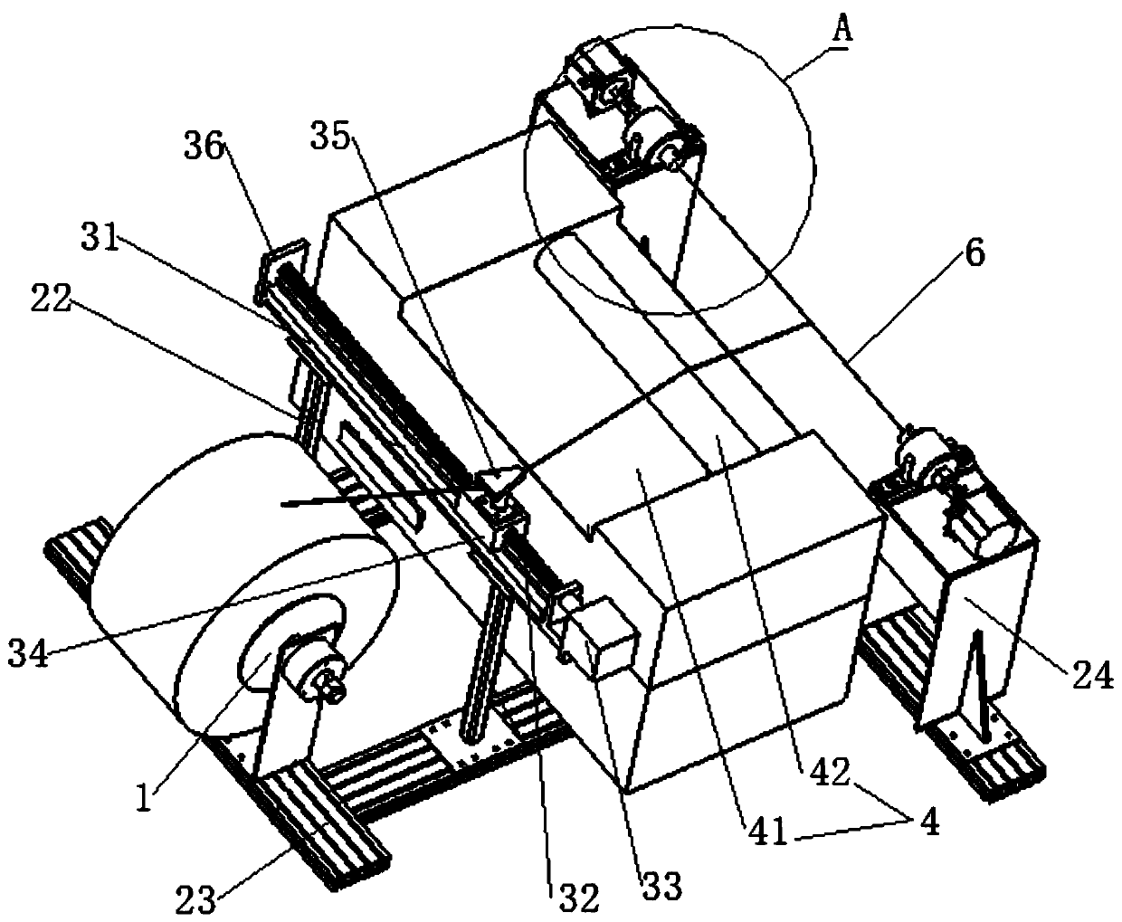
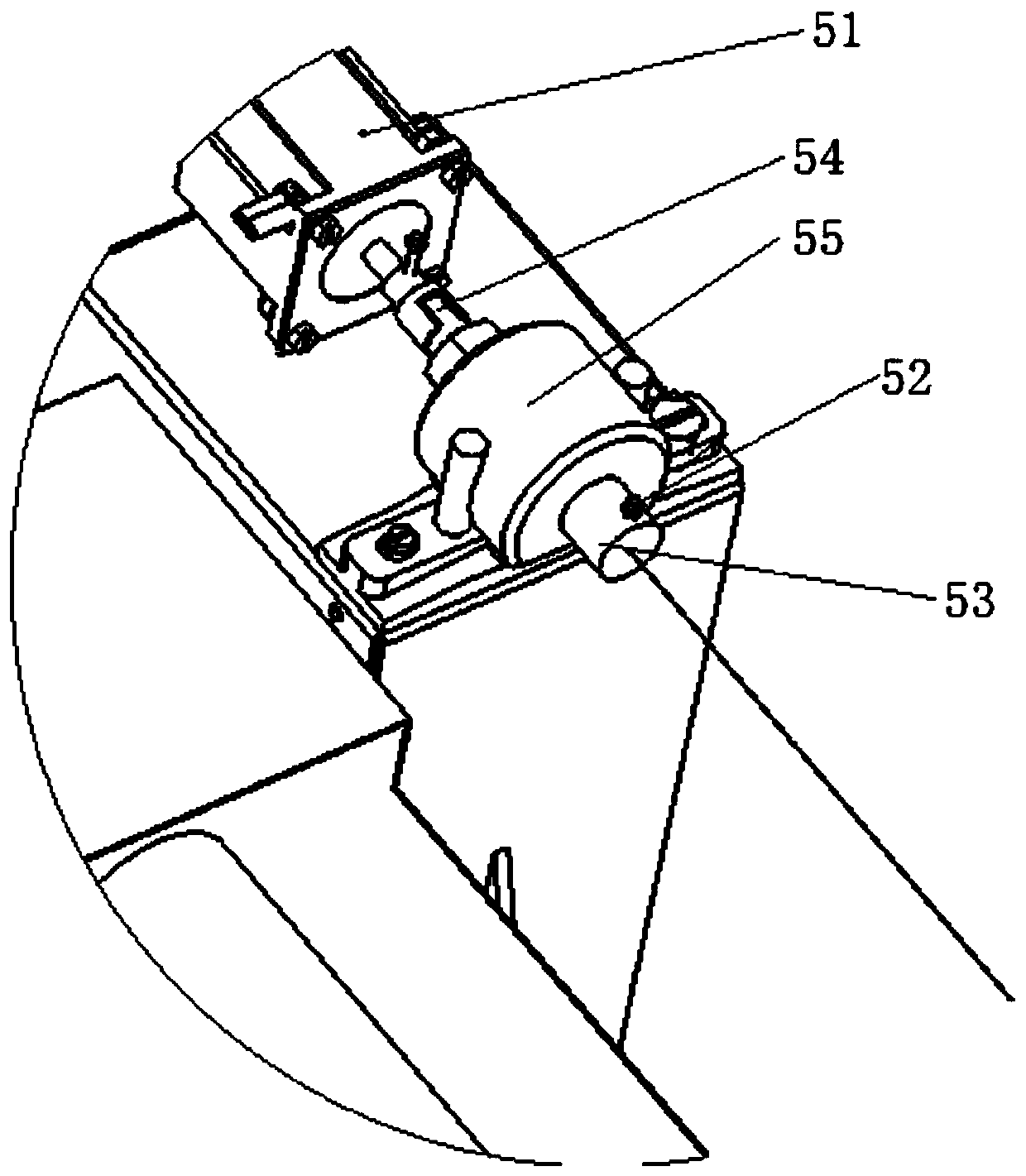
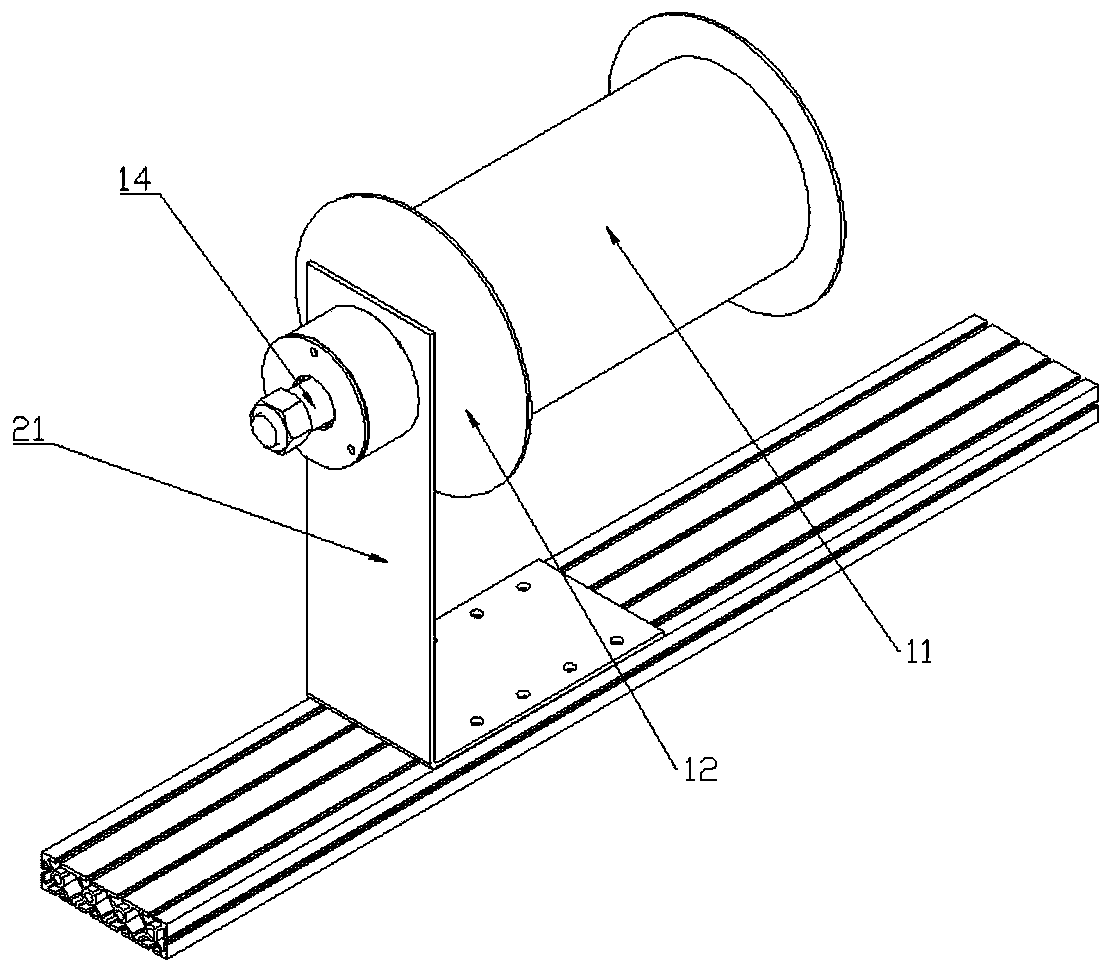
[0072] like figure 1 As shown, a processing device for plugging fiber particles includes a support frame, and an on-line mechanism 1 connected to the support frame, a glue hanging mechanism 4, a wiring mechanism and a rotating clamping mechanism, and the glue hanging mechanism 4 and the wiring mechanism are all provided with Between the upper thread mechanism 1 and the rotary clamping mechanism.

[0073] On-line mechanism 1, the on-line mechanism 1 is used to place fiber coils wound by fiber threads.

[0074] The rotating clamping mechanism is used to drive the steel wire 6 to rotate, and to wind the fiber thread around the steel wire 6 .

[0075] Wiring mechanism, the wiring mechanism is arranged between the glue hanging mechanism 4 and the threading mechanism 1, and the wiring mechanism is used to control the movement of the fiber wire along the axis of the steel wire 6, so that the fiber wire is evenly wound on the steel wire 6.

[0076] A glue-hanging mechanism 4, the gl...

Embodiment 2

[0079] like Figure 1-3 Shown, a kind of processing method of the processing device of plugging fiber particle, comprises the following steps:

[0080] Step A: Wrap the fiber wire around the steel wire 6 .

[0081] Step B: Fix the fiber thread and the steel wire 6 .

[0082] Step C: cutting the shaped fiber strands and steel wires 6 into sections to form granules.

Embodiment 3

[0084] like Figure 1-3 As shown, a processing device for plugging fiber particles includes a support frame, and an on-line mechanism 1 connected to the support frame, a glue hanging mechanism 4, a wiring mechanism and a rotating clamping mechanism, and the glue hanging mechanism 4 and the wiring mechanism are all provided with Between the upper thread mechanism 1 and the rotary clamping mechanism.

[0085] On-line mechanism 1, the on-line mechanism 1 is used to place fiber coils wound by fiber threads.

[0086] The rotating clamping mechanism is used to drive the steel wire 6 to rotate, and to wind the fiber thread around the steel wire 6 .

[0087] Wiring mechanism, the wiring mechanism is arranged between the glue hanging mechanism 4 and the threading mechanism 1, and the wiring mechanism is used to control the movement of the fiber wire along the axis of the steel wire 6, so that the fiber wire is evenly wound on the steel wire 6.

[0088] A glue-hanging mechanism 4, the...


PUM

PropertyMeasurementUnit
lengthaaaaaaaaaa
diameteraaaaaaaaaa
diameteraaaaaaaaaa

Abstract

The invention belongs to the technical field of machining, and discloses a machining device of leaking stoppage fiber particles. The device comprises a supporting frame, a line feeding mechanism, a glue coating mechanism, a line distribution mechanism and a rotary clamping mechanism, wherein the line feeding mechanism, the glue coating mechanism, the line distribution mechanism and the rotary clamping mechanism are connected with the supporting frame; the glue coating mechanism and the line distribution mechanism are arranged between the line feeding mechanism and the rotary clamping mechanism; the line feeding mechanism is used for storing fiber rolls wound by fiber lines; the rotary clamping mechanism is used for driving steel wires to rotate and winding the fiber lines onto the steel wires; and the glue coating mechanism is arranged between the line distribution mechanism and the rotary clamping mechanism and used for coating glue to the fiber lines. By arrangement of the multiple mechanisms, automatic winding of the fiber lines is achieved, the winding speed of the fiber lines is increased, the winding quality is improved, and high efficiency is achieved on the premise of saving cost.

Description

technical field [0001] The invention belongs to the technical field of mechanical processing, and in particular relates to a processing device for plugging fiber particles and a method for processing plugging fiber particles. Background technique [0002] Drilling plugging is a problem that often needs to be solved in production. Different geological conditions and different drilling plugging conditions use different plugging materials. One of the plugging materials being tested is to wind different plastic fiber threads on a 0.2-0.4mm steel wire, the diameter of which is not more than 2mm after winding, and then cut into sections with a size of about 2mm after the surface is glued and dried. Become particles with a particle diameter of about 2mm. After the particles absorb water in the water, they expand greatly to achieve the purpose of plugging. At present, different plastic fiber threads are manually wound on 0.2-0.4mm steel wires, the efficiency is very low, and the ...

Claims


Application Information

Patent Timeline
Patent Type & Authority Applications(China)
IPC IPC(8): B21F11/00B65H81/06
Inventor 尹锐张瑞明张晓东陈树刚贾溪蕊
Owner SCI RES TRAINING CENT FOR CHINESE ASTRONAUTS
Learn More