Plate cutting machine

A technology of trigger and sheet material, which is applied in the field of panel opening machine, can solve the problems of scattered panels, high requirements, and long production line of panel opening machine, so as to meet the requirements of reducing the floor area of ​​the factory building and reduce the cost of enterprise employment , the effect of shortening the distance between the head and the tail

Active Publication Date: 2019-05-03
浙江容健科技有限公司
View PDF8 Cites 4 Cited by
  • Summary
  • Abstract
  • Description
  • Claims
  • Application Information

AI Technical Summary

Problems solved by technology

[0003] At present, the opening machines on the market have the following problems: 1. When the opening machine cuts the large cardboard, it needs to go through the feeding of the large cardboard, the first cutting, the conveying of the strip, and the second cutting , small cardboard conveying and sorting, and the existing board opening machine usually arranges each process in a row to form a production line, so the production line of the board opening machine is pulled extremely long, and the narrow and long overall structure has a negative impact on the factory building. In addition, the distance between the beginning and the end of the opening machine production line is long, which is not convenient for the operator to take care of both ends, and also increases the labor intensity of the operator.
[0004] 2. After the plate is cut, the plate opening machine needs to be sorted and packed manually. It will not use machinery to unload the cut plate in a regular manner, but directly let the cut plate itself drop, and the plate after falling Scattered, very chaotic, and then manually stacked, stored, or transported to subsequent processing machinery by subsequent workers, so this directly increases the labor intensity of workers and also increases the input cost of personnel

Method used


Image

  • Plate cutting machine
  • Plate cutting machine
  • Plate cutting machine

Examples


Embodiment Construction

[0029] The present invention will be described in further detail below in conjunction with the accompanying drawings and embodiments. Wherein the same components are denoted by the same reference numerals. It should be noted that the words "front", "rear", "left", "right", "upper" and "lower" used in the following description refer to the directions in the drawings, and the words "bottom" and "top "Face", "inner" and "outer" refer to directions toward or away from, respectively, the geometric center of a particular component.

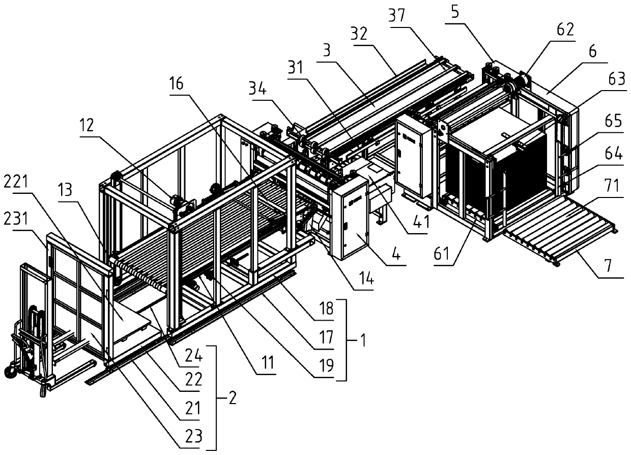
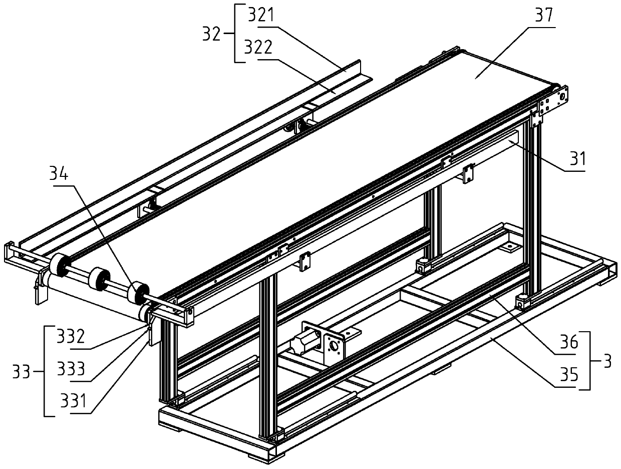
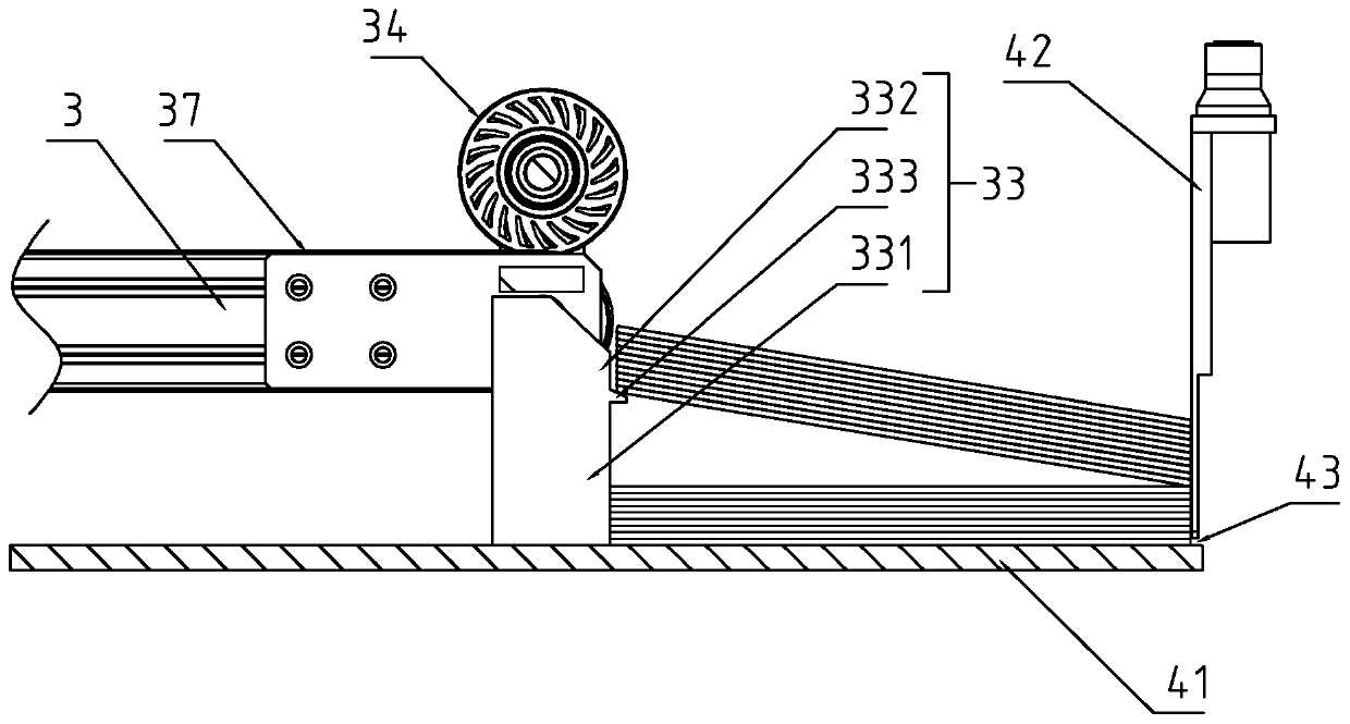
[0030] refer to Figure 1-10 As shown, a plate opening machine includes two circular knife slitters and a feeding device that can push large plates into the first circular knife slitter 5, wherein the two circular knife slitters can The cardboard is cut along the direction of its conveyance, and the L-shaped conveyance of the cardboard is realized by setting a sheet material turning device between the two circular knife slitters. The specific conveyin...


PUM


Abstract

The invention discloses a plate cutting machine. The plate cutting machine comprises a first circular cutter slitting machine, a feeding device, a second circular cutter slitting machine and a plate steering frame; the plate steering frame is rotationally connected with a steering conveying belt; a feed port of the plate steering frame is positioned on one side; a discharge port of the plate steering frame is positioned at one end; a plate arrangement mounting frame, a plate arrangement conveying table, a plate arrangement conveying belt and a plate placing tray are arranged at a discharge endof the second circular cutter slitting machine; one end of the plate arrangement conveying table is rotationally connected to the plate arrangement mounting frame; a plate arrangement rotating mechanism is arranged on the plate arrangement mounting frame, and can drive the end, far from the slitting machine, of the plate arrangement conveying table to move in the height direction; and a plate collecting shelf is arranged at a discharge end of the plate arrangement conveying table, and comprises a plate collecting guide rail, a plate collecting base and a plate collecting driving mechanism. The plate cutting machine can reduce the arrangement length of a whole production line to reduce the requirements on factory buildings, and can realize automatic arrangement of plates.

Description

technical field [0001] The present invention relates to the technical field of plate processing mechanical devices, more specifically, it relates to a plate opening machine. Background technique [0002] The cardboards of high-end bookcases, diaries, children's book-shaped boxes and other hard-shell products produced in China all need small cardboards. These small cardboards need to go through the process of cutting large cardboards into small cardboards. The machine is used to cut large cardboard raw materials into small-sized cardboards that meet the requirements of subsequent processes. [0003] At present, the opening machines on the market have the following problems: 1. When the opening machine cuts the large cardboard, it needs to go through the feeding of the large cardboard, the first cutting, the conveying of the strip, and the second cutting , small cardboard conveying and sorting, and the existing board opening machine usually arranges each process in a row to f...

Claims


Application Information

Patent Timeline
Patent Type & Authority Applications(China)
IPC IPC(8): B31B50/20B31B50/74B31B50/04
Inventor 吴应义蔡希海吴应忠蔡锦波王作将何新义
Owner 浙江容健科技有限公司
Why Eureka
Try Eureka