Head-up display device, driving method, vehicle and electronic device

A head-up display and driving method technology, applied in the fields of electronic equipment and vehicles, can solve problems such as hidden safety hazards and inability to realize automatic adjustment, and achieve the effect of reducing the probability of danger and reducing the switching time.

Active Publication Date: 2019-05-03
BOE TECH GRP CO LTD
View PDF6 Cites 5 Cited by
  • Summary
  • Abstract
  • Description
  • Claims
  • Application Information

AI Technical Summary

Problems solved by technology

[0003] Although the existing head-up display system can project the image to be displayed onto the front windshield, the distance between the virtual image p

Method used


Image

  • Head-up display device, driving method, vehicle and electronic device
  • Head-up display device, driving method, vehicle and electronic device
  • Head-up display device, driving method, vehicle and electronic device

Examples


Embodiment 1

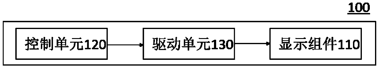
[0058] see figure 1 , which exemplarily shows a simplified block diagram of the head-up display device 100 according to the embodiment of the present invention. Specifically, the head-up display device includes: a display component 110 , a control unit 120 and an execution unit 130 .

[0059] Among them, the display assembly 110 is used to display images, and the control unit 120 is used to obtain the real-time speed of the vehicle and generate and output the image distance control signal according to the real-time speed of the vehicle; the execution unit 130 is connected with the display assembly 110 and the control unit 120 for The display assembly 110 is driven according to the image distance control signal generated by the control unit 120 , and the image distance of the image displayed by the display assembly 110 is controlled to change with the change of the real-time vehicle speed.

[0060]In the prior art, when the vehicle is running, the display component of the head...

Embodiment 2

[0112] According to the second embodiment of the present invention, there is also provided a driving method for the head-up display system described in any one of the above embodiments. Such as Figure 6 As shown, it schematically shows a flowchart of a driving method for a head-up display system according to an embodiment of the present invention, and the driving method may include the following steps:

[0113] S1. Obtain the real-time speed of the vehicle;

[0114] S2. Generate an image distance control signal according to the real-time speed of the vehicle, so that the image distance of the image displayed by the head-up display device changes according to the change of the real-time vehicle speed.

[0115] In an optional embodiment, the above-mentioned driving method may also include the following steps:

[0116] S3. Generate an angle control signal according to the real-time vehicle speed of the vehicle, so as to adjust the bird's-eye view angle of the image displayed b...

Embodiment 3

[0126] According to Embodiment 3 of the present invention, a vehicle is further provided, and the vehicle includes the head-up display device provided in Embodiment 1 of the present invention.


PUM


Abstract

The invention provides a head-up display device, a driving method, a vehicle and an electronic device. The head-up display device includes a display assembly, a control unit and an execution unit, wherein the display assembly is used to output a display image; the control unit is used to acquire a real-time vehicle speed of the vehicle and generate an image distance control signal according to thereal-time vehicle speed of the vehicle; the execution unit is connected to the display assembly for adjusting the display assembly according to the image distance control signal and controlling the image distance of the image displayed by the display assembly to change according to the change of the real-time vehicle speed; the control unit is further used to generate an angle control signal according to the real-time vehicle speed of the vehicle; and the execution unit is further used to drive the display assembly according to the angle control signal and adjust a top view angle of the imagedisplayed by the display assembly. The technical solution of the head-up display device can reduce the switching time between the normal driving and watching of the image displayed by the head-up display device for the driver, thus reducing the probability of occurrence of danger.

Description

technical field [0001] The present invention relates to the field of display technology, in particular to a head-up display device, a driving method of the head-up display device, a vehicle and an electronic device. Background technique [0002] Head Up Display (HUD) has gradually been widely used in the automotive field. The head-up display is to project the important information (such as vehicle speed, navigation, etc.) displayed on the instrument during the driving of the car onto the front windshield, so that the driver can see the information in the instrument without looking down, which can not only help the inexperienced in judging the speed Novices can control their speed to avoid violating regulations due to speeding in speed-limited sections. More importantly, it can enable the driver to read instantly without shifting the large field of view, and always maintain the best observation state, avoiding the driver looking down. When the instrument display or audio dis...

Claims


Application Information

Patent Timeline
IPC IPC(8): B60R1/00G02B27/01
CPCB60K35/00B60K2370/1529B60K2370/167G02B27/0101G02B2027/0183G02B2027/014G02B2027/0138B60K2370/50G02B27/0179
Inventor 于越衣祝松
Owner BOE TECH GRP CO LTD
Why Eureka
Try Eureka