
Impulse type cycle engine

A pulsed, engine technology, applied in the field of aircraft drive, can solve the problems of inability to meet the long-distance drive capability, difficulty in large-scale preparation of antimatter fuel, and difficulty in storage.

Inactive Publication Date: 2019-05-03
李超
View PDF13 Cites 0 Cited by
  • Summary
  • Abstract
  • Description
  • Claims
  • Application Information

AI Technical Summary

Problems solved by technology

In the space environment, this driving method has two problems: one is that there is almost no usable medium in space, although solar sails can use sunlight, but the efficiency is extremely low
Second, the specific impulse of chemical energy propulsion determines that no matter how large the driving target is, it cannot carry enough disposable working medium while satisfying the remote driving capability
The third is that the chemical specific impulse propulsion can only reach the second cosmic speed, and the maximum speed that can be propelled is only more than ten kilometers per second, which cannot directly drive the aircraft to fly away from the solar system
The existing space drive mode has become a bottleneck, whether it is high specific impulse rockets, electrochemical engines, solar sails, or gravity-accelerated orbit-changing technologies, they cannot fundamentally solve the problem of driving long-distance space vehicles
Antimatter engines are not very safe, and antimatter fuel is not easy to prepare on a large scale, and it is extremely difficult to store them in large quantities.

Method used


Image

  • Impulse type cycle engine
  • Impulse type cycle engine
  • Impulse type cycle engine

Examples


Embodiment 1

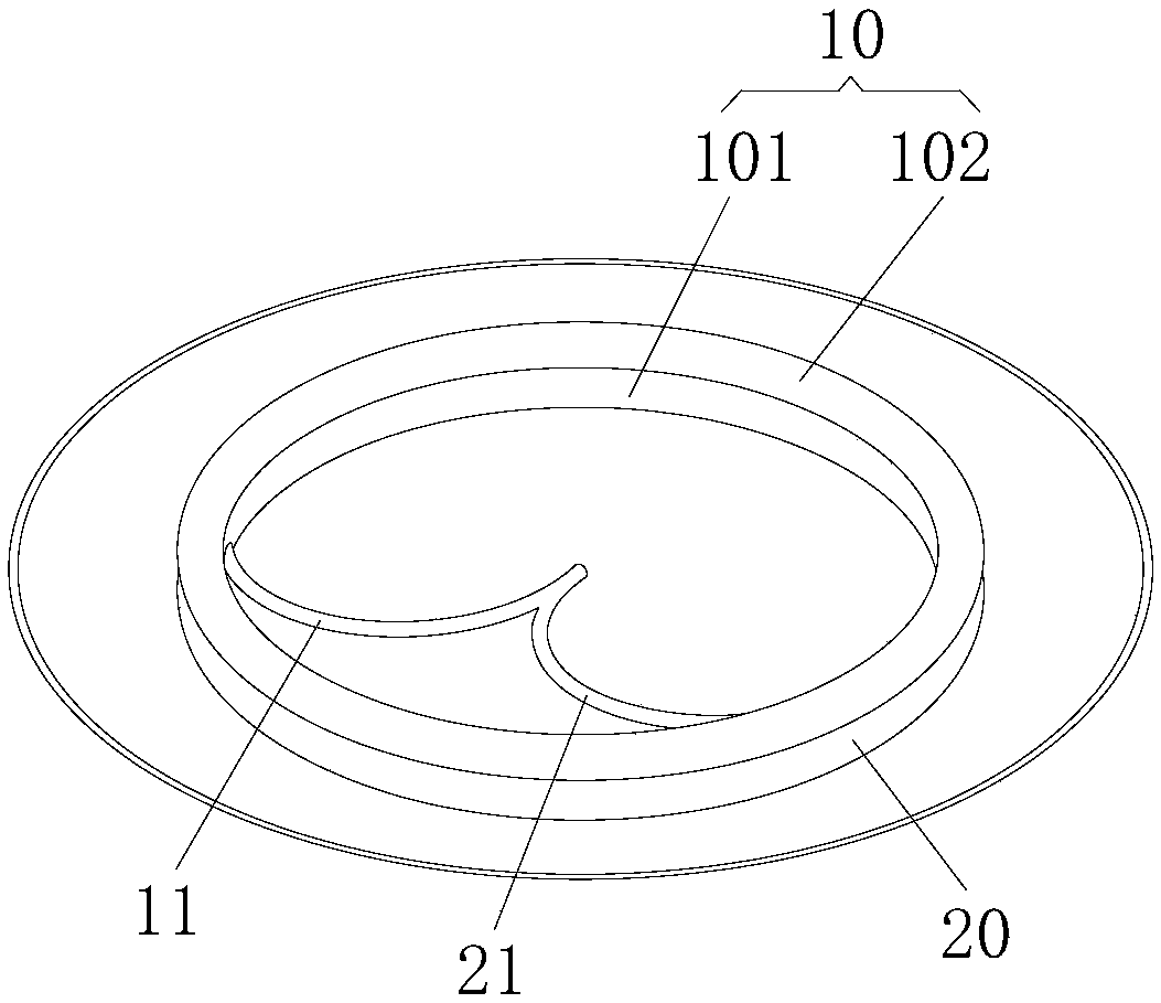
[0029] see figure 1 , the pulse type impulse cycle engine provided by the present invention is now described. The pulse-type impulse cycle engine includes an acceleration device 10 . The accelerating device 10 can accelerate the particle beam in its tube to a high sub-light velocity state. The high sub-light speed state of the particles refers to the state close to the speed of light, that is, the speed of the particles is greater than 90% of the speed of light and less than the speed of light. Accelerate the particle beam in a high-frequency group mode, and output multiple batches of accelerated particle beams in a periodic manner, so that the acceleration driving force is more uniform. Optionally, before the particle beam enters the accelerating device 10 , a linear accelerator can be set to accelerate and adjust the particle beam, so as to improve the quality of the incident particle beam entering the accelerating device 10 . Among them, when the particles in the particl...

Embodiment 2

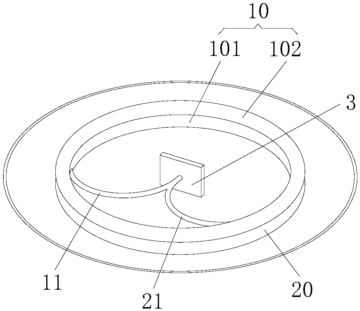
[0036] read on figure 2 , as an impulse cycle engine provided in Embodiment 2 of the present invention, the impulse cycle engine may also include a deflection plate 3, the deflection plate 3 is used to receive the impact of the particle beam discharged from the first guide pipe 11 or the second guide pipe 21, The kinetic energy of the particle beam is transmitted to the deflection disk 3, and the angle of the deflection disk 3 is adjusted to control the direction of motion of the aircraft. The propulsion method of this kind of aircraft is referred to as indirect propulsion.

[0037] Further, see figure 1 and figure 2 , as a pulsed impulse cycle engine provided in Embodiment 2 of the present invention, the central axis of the first circular accelerator 101 coincides with the central axis of the second circular accelerator 102 . Specifically, the first circular accelerator 101 and the second circular accelerator 102 are arranged in parallel, and assuming that a certain plane...

Embodiment 3

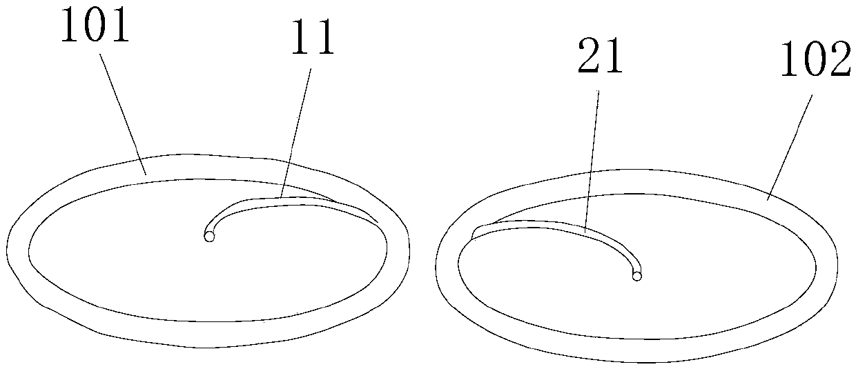
[0039] see image 3 , as a pulse type impulse cycle engine provided in Embodiment 3 of the present invention, the difference from Embodiment 2 is that the first circular accelerator and the second circular accelerator are arranged on the same plane, which can also eliminate the Torque to avoid aircraft imbalance. Certainly, in other embodiments, the first circular accelerator and the second circular accelerator may also be symmetrically arranged on different planes, which is not limited here.


PUM


Abstract

The invention provides an impulse type cycle engine which comprises an accelerating device used for accelerating a particle beam to a high sublight speed state. After the particle beam is acceleratedin the accelerating device to obtain high-speed kinetic energy and extra mass, the particle beam is discharged through a spray pipe to propel an aircraft to go forward. According to the impulse type cycle engine, particles are accelerated to high sublight speed to obtain great impulse to propel the aircraft. Different from propulsion of a chemical specific impulse mode, the impulse type cycle engine does not need to carry a large disposable working medium and is suitable for remote driving.

Description

technical field [0001] The invention belongs to the technical field of aircraft drive, and more specifically relates to a pulse type impulse cycle engine. Background technique [0002] Almost all current space-driven methods rely on directly discarding the working medium or driving a certain medium in the environment. In the space environment, there are two problems with this driving method: one is that there is almost no usable medium in space. Although solar sails can use sunlight, their efficiency is extremely low. Second, the specific impulse of chemical energy propulsion determines that no matter how large the driving target is, it cannot carry enough disposable working medium while satisfying the remote driving capability. The third is that the chemical specific impulse propulsion method can only reach the second cosmic speed, and the maximum speed that can be propelled is only more than ten kilometers per second, which cannot directly drive the aircraft to fly away f...

Claims


Application Information

Patent Timeline
Patent Type & Authority Applications(China)
IPC IPC(8): F03H1/00
CPCF03H1/00
Inventor 李超
Owner 李超
Learn More