Novel ball screw rod device

A ball screw, a new type of technology, applied in the direction of transmission, belt/chain/gear, mechanical equipment, etc., can solve the problem of scars on the contact surface between the screw and the nut, inconvenient oiling and lubrication of parts, and narrowing of the internal moving space to achieve lubrication. The effect is good, the processing surface of the slide seat is reduced, and the assembly time is shortened

Pending Publication Date: 2019-05-03
深圳市锐健电子有限公司
View PDF30 Cites 0 Cited by
  • Summary
  • Abstract
  • Description
  • Claims
  • Application Information

AI Technical Summary

Problems solved by technology

[0004] 1) The installation of the ball screw is relatively complicated, requiring technicians with certain processing accuracy and calibration ability to install, and the installation efficiency is low;
[0005] 2) There must be a nut seat between the sliding seat and the screw rod, and it needs to use a flange structure, and then lock it with a few screws. When the screw is locked in a narrow installation space, it is easy to cause inaccurate positioning of the screw hole , it needs to be debugged repeatedly;
[0006] 3) It needs to be installed with the help of a flange structure and several screws, resulting in a large space occupied by the entire device. In the limited assembly space, the actual internal movement space of each part will be reduced, which directly affects the operation of the entire device;
[0007] 4) The parts are basically hidden in the device, and it is very inconvenient to lubricate the parts; and the ball screw is used for a long time, if it is impossible to add lubricating oil, it will easily cause hard friction of the parts, and cause the contact surface between the screw and the nut Scars, leading to problems such as deviation of walking accuracy and uneven stability;
[0008] 5) During production and installation, many parts are required, resulting in a large, clumsy, and low practicability of the entire device
[0009] In summary, the ball screw has the problem of inconvenience in practice, so it is necessary to improve it

Method used


Image

  • Novel ball screw rod device
  • Novel ball screw rod device
  • Novel ball screw rod device

Examples


Embodiment Construction

[0060] The present invention will be described in detail below in conjunction with the accompanying drawings and specific embodiments.

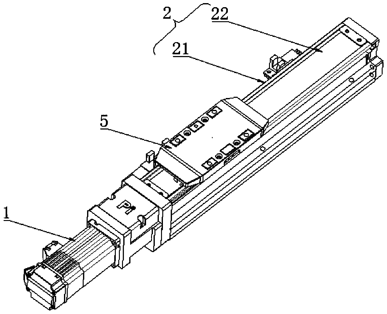
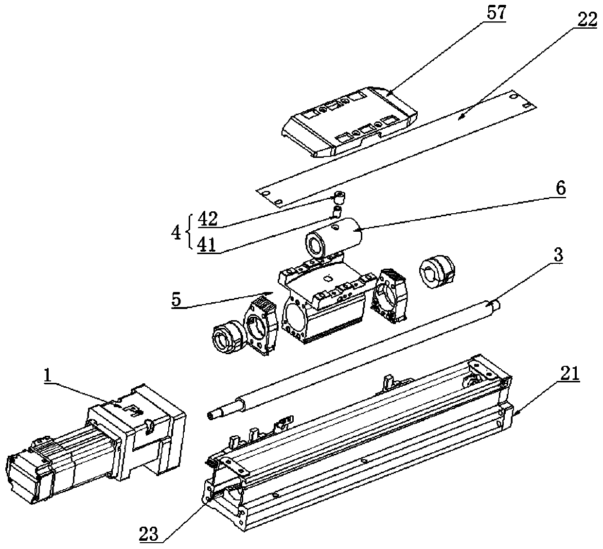
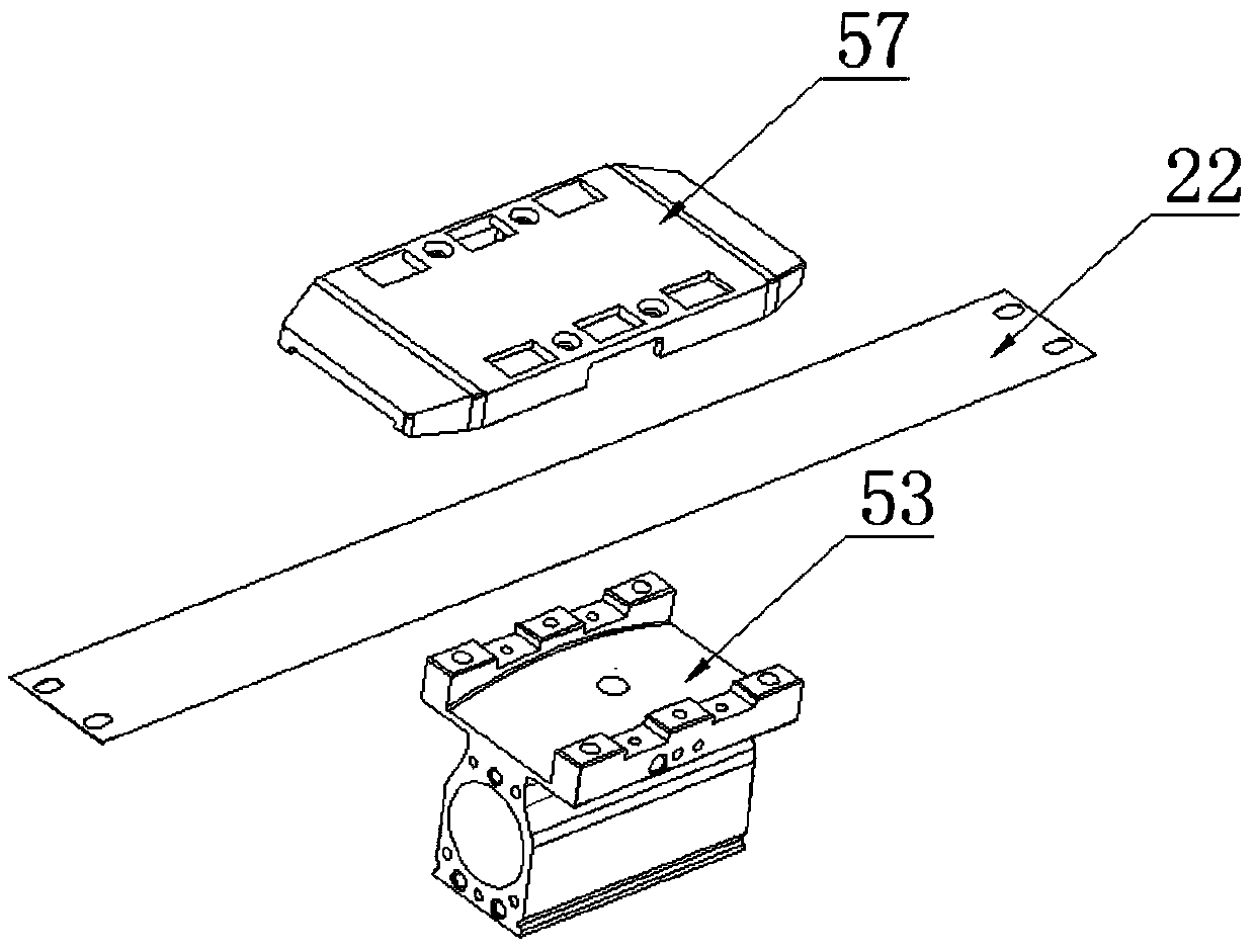
[0061] refer to Figures 1 to 9 As shown, the present invention provides a new type of ball screw device, including a motor 1, a screw 3, a nut 6, a slide 5, and a pin assembly 4; the middle of the slide 5 is provided with a mounting hole, and the nut 6 is coaxial Embedded in the installation hole; the screw rod 3 passes through the installation hole and is screwed with the nut 6; the top of the slide seat 5 is provided with a first through hole 52, and the position corresponding to the first through hole 52 on the side of the nut 6 A pin hole 321 is provided; the pin assembly 4 is used to fixedly connect the nut 6 with the sliding seat 5 through the first through hole 52 and the pin hole 321; the sliding seat 5 is also provided with several oil storage tanks, several flow channels, and several The flow channel is used to communicate with seve...


PUM


Abstract

The invention discloses a novel ball screw rod device. The novel ball screw rod device comprises a motor, a screw rod, a nut, a sliding seat and a plug pin assembly; a mounting hole is formed in the middle of the sliding seat, and the nut is coaxially embedded into the mounting hole; the screw rod penetrates through the mounting hole and is in screw connection with the nut; a first through hole isformed in the top of the sliding seat, and a plug pin hole is formed in the position, corresponding to the first through hole, of the periphery side of the nut; the plug pin assembly is used for fixedly connecting the nut and the sliding seat through the first through hole and the plug pin hole; the sliding seat is further provided with a plurality of oil storage tanks and a plurality of flow channels, and the flow channels are used for communicating with the oil storage tanks to pump in lubricating oil; and the motor is used for driving the screw rod to drive the sliding seat to slide through the nut. The novel ball screw rod device is convenient to assemble and convenient to lubricate, has a compact structure, saves cost and has high practicability.

Description

technical field [0001] The invention relates to the technical field of ball screws, in particular to a novel ball screw device. Background technique [0002] Ball screw is the most commonly used transmission element in tool machinery and precision machinery. Its main function is to convert rotary motion into linear motion, or convert torque into axial repeated force. It also has high precision, reversibility and high precision. Features of efficiency. Due to its small frictional resistance, ball screws are widely used in various industrial equipment and precision instruments. [0003] At present, most of the ball screw devices on the market have the following deficiencies: [0004] 1) The installation of the ball screw is relatively complicated, requiring technicians with certain processing accuracy and calibration ability to install, and the installation efficiency is low; [0005] 2) There must be a nut seat between the sliding seat and the screw rod, and it needs to us...

Claims


Application Information

Patent Timeline
Patent Type & Authority Applications(China)
IPC IPC(8): F16H25/22F16H57/04
Inventor 张贺兴
Owner 深圳市锐健电子有限公司
Why Eureka
Try Eureka