Tunable E-surface cutting H-surface waveguide band-pass filter and design method thereof

A technology of band-pass filter and design method, which is applied to waveguide-type devices, electrical components, circuits, etc., can solve the problems of filter consistency and insufficient precision frequency response performance.

Pending Publication Date: 2019-05-03
CHANGZHOU INST OF MECHATRONIC TECH
View PDF0 Cites 3 Cited by
  • Summary
  • Abstract
  • Description
  • Claims
  • Application Information

AI Technical Summary

Problems solved by technology

[0007] The present invention proposes a tunable E-plane cut H-...

Method used


Image

  • Tunable E-surface cutting H-surface waveguide band-pass filter and design method thereof
  • Tunable E-surface cutting H-surface waveguide band-pass filter and design method thereof
  • Tunable E-surface cutting H-surface waveguide band-pass filter and design method thereof

Examples


Embodiment 1

[0079] A design method of a tunable E-plane cut H-plane waveguide bandpass filter, the process of the design method is as follows:

[0080] According to the microwave filter network theory, all types of filters, such as maximum flatness, Chebyshev, and elliptic function filters, can be mapped into normalized low-pass prototype filters. Compared with the maximum flat filter, the Chebyshev filter has the advantage of equal ripple in the band. Although the performance of the elliptic function type filter is better, it is generally difficult to implement, so this article discusses the Chebyshev type bandpass filter.

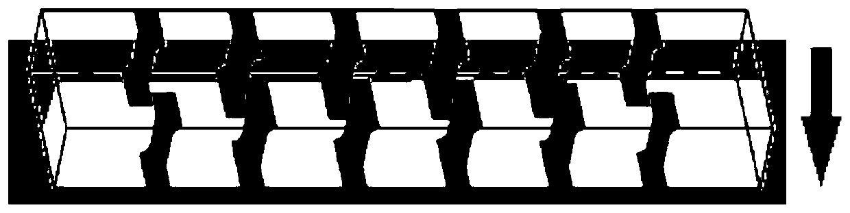
[0081] The H filter uses the waveguide section of half the waveguide wavelength as the series resonator, and uses the parallel inductance formed by the inductance diaphragm as the coupling structure between the resonators, such as figure 1 shown.

[0082] From equations (1) to (3), the approximate conversion formula from low-pass prototype to band-pass filter can b...

Embodiment 2

[0136] A tunable E-plane cut H-plane waveguide bandpass filter formed by the design method, such as figure 1 As shown, the tunable E-plane cut H-plane waveguide bandpass filter includes an H-plane waveguide bandpass filter and an upper cover: the H-plane waveguide bandpass filter adopts a rectangular structure; the H-plane waveguide bandpass filter There are two groups of inductance diaphragms inside the device, and each group of inductance diaphragms includes two rows of inductance diaphragms; the two groups of inductance diaphragms are mirror-symmetrically distributed with the central axis on the long side of the H-plane waveguide bandpass filter as the symmetry axis Inside the H-plane waveguide band-pass filter; two rows of inductance diaphragms in each group of inductance diaphragms are mirror-symmetrically installed on the H-plane waveguide band with the central axis on the wide side of the H-plane waveguide band-pass filter as the symmetrical axis The long side walls on ...


PUM


Abstract

The invention provides a tunable E-surface cutting H-surface waveguide band-pass filter and a design method thereof, and belongs to the technical field of filter design. The method comprises steps offrom a lumped parameter low-pass prototype, establishing a model with chamfering; after frequency transformation, deriving a new design formula of a coupled resonator band-pass filter with a chamferedlumped parameter; using a microwave structure to implement the coupling structures and resonators to obtain a microwave band-pass filter. The method ensures low loss of the filter without band offset. Compared with a traditional method, the method solves large errors and high losses. The method is widely used in the fields of short-range air defense, battlefield surveillance, missile guidance, airborne collision avoidance, high-resolution imaging, space target detection, battlefield identification, and millimeter wave communication.

Description

technical field [0001] The invention relates to a tunable E-plane cut H-plane waveguide bandpass filter and a design method thereof, belonging to the technical field of filter design. Background technique [0002] All kinds of objects in nature radiate electromagnetic waves. Both theoretical analysis and experimental measurements in the millimeter wave band show that there are huge differences in the ability of different objects to radiate millimeter waves. Therefore, if the millimeter-wave radiation information of an object can be obtained, the shape, volume, distance, and even material characteristics of the object can be inferred to a certain extent, which is beneficial to target detection and identification, war coordination, automatic navigation, and anti-stealth technologies. are all important. Passive millimeter-wave imaging technology is a means to obtain millimeter-wave radiation images of objects or scenes. The millimeter-wave energy radiated by the scene to be i...

Claims


Application Information

Patent Timeline
IPC IPC(8): H01P1/208
Inventor 杨保华邹华杰王云良吴红亚楼竞
Owner CHANGZHOU INST OF MECHATRONIC TECH
Why Eureka
Try Eureka