Puncture needle
A puncture needle and needle core technology, applied in the field of puncture needles, can solve problems such as organ or tissue damage, tumor metastasis, etc., and achieve the effects of reducing the probability of metastasis, alleviating pain, and reducing the difficulty of operation.
- Summary
- Abstract
- Description
- Claims
- Application Information
AI Technical Summary
Problems solved by technology
Method used
Image
Examples
Embodiment 1
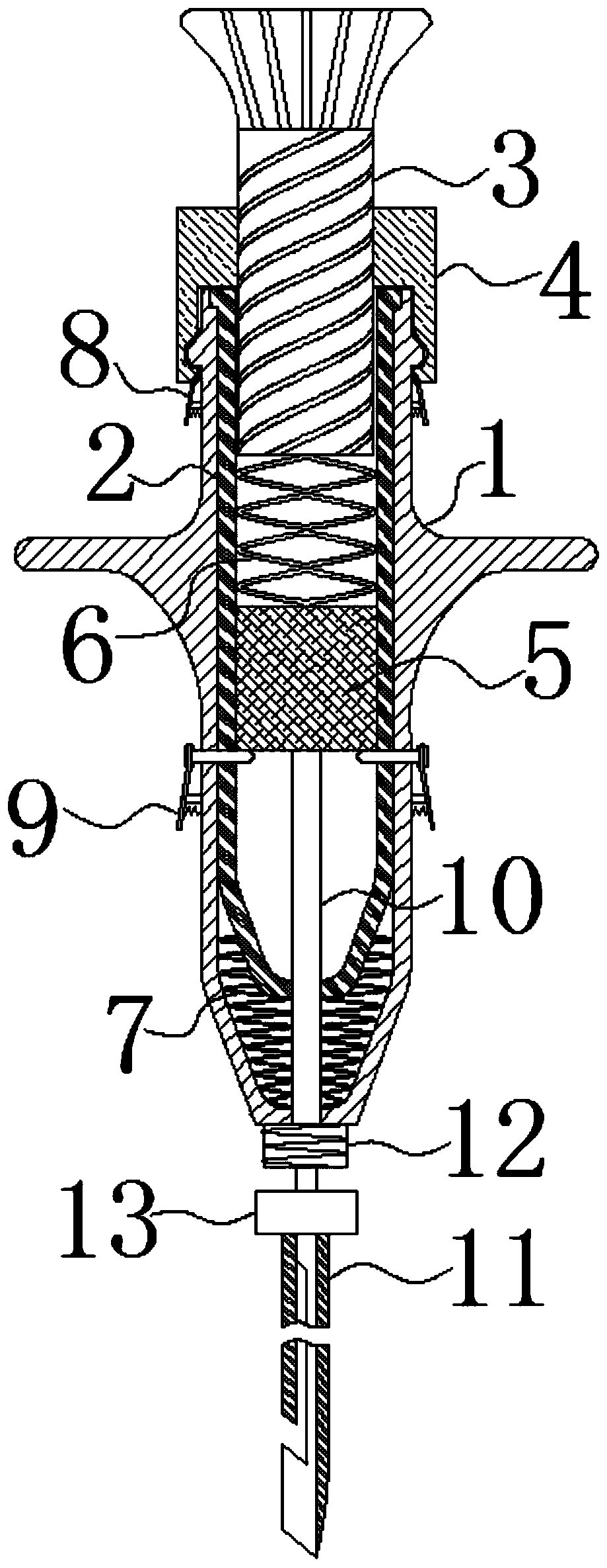
[0037] a puncture needle such as figure 1 As shown, it includes a needle tube, a pusher 3, a needle core 10 and a needle head 11, the needle tube has an inner thread, the pusher 3 has an outer thread adapted to the inner thread, and the pusher 3 can rotate on the inner thread of the needle tube to realize the Advance and retract functions. The needle tube is connected with the needle head 11 , the needle core 10 is sleeved in the needle head 11 , and the needle core 10 can slide freely relative to the needle head 11 . The pusher 3 is connected with the needle core 10, and the pusher 3 can rotate freely relative to the needle core 10, for example, the pusher 3 is connected with the needle core 10 through a bearing. When the pusher 3 rotates through the thread in the needle tube, the pusher 3 can drive the needle core 10 to advance or retract in the needle head 11 .
[0038] like Image 6 As shown, during the biopsy puncture operation, when the needle 11 reaches the set punct...
Embodiment 2
[0040] As preferably, in order to better realize the present invention, further optimization is carried out on the basis of the above-mentioned embodiment, and the following setting structure is particularly adopted:
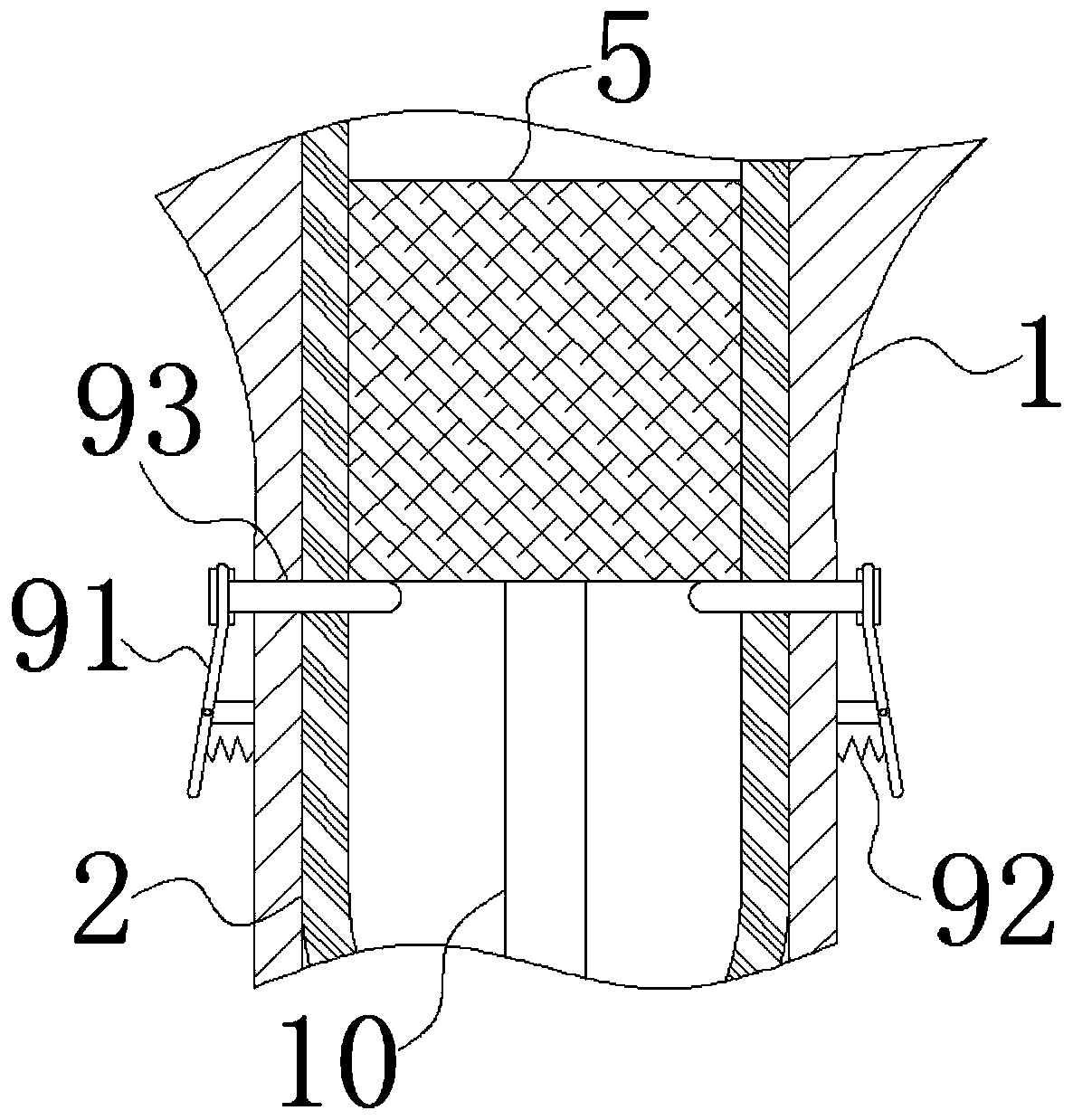
[0041] like figure 1 and figure 2 As shown, a first ejection device and a first fixing device 9 are arranged in the needle tube, the first ejection device includes a conversion plug 5 and a first spring 6, the needle core 10 is installed on the conversion plug 5, and the first spring 6 is installed in the pusher between the device 3 and the conversion plug 5. The first fixing device 9 includes a button 91 and a spring 92. The middle of the button 91 is hinged to the outer wall of the needle tube through a column, and the spring 92 is connected between one side of the button a 91 and the outer wall of the needle tube. The other side of 91 is connected to the restraining member 93 . The restraining piece 93 can be a blade or a pin, and the restraining piece 93...
Embodiment 3
[0045] As preferably, in order to better realize the present invention, further optimization is carried out on the basis of the above-mentioned embodiment, and the following setting structure is particularly adopted:
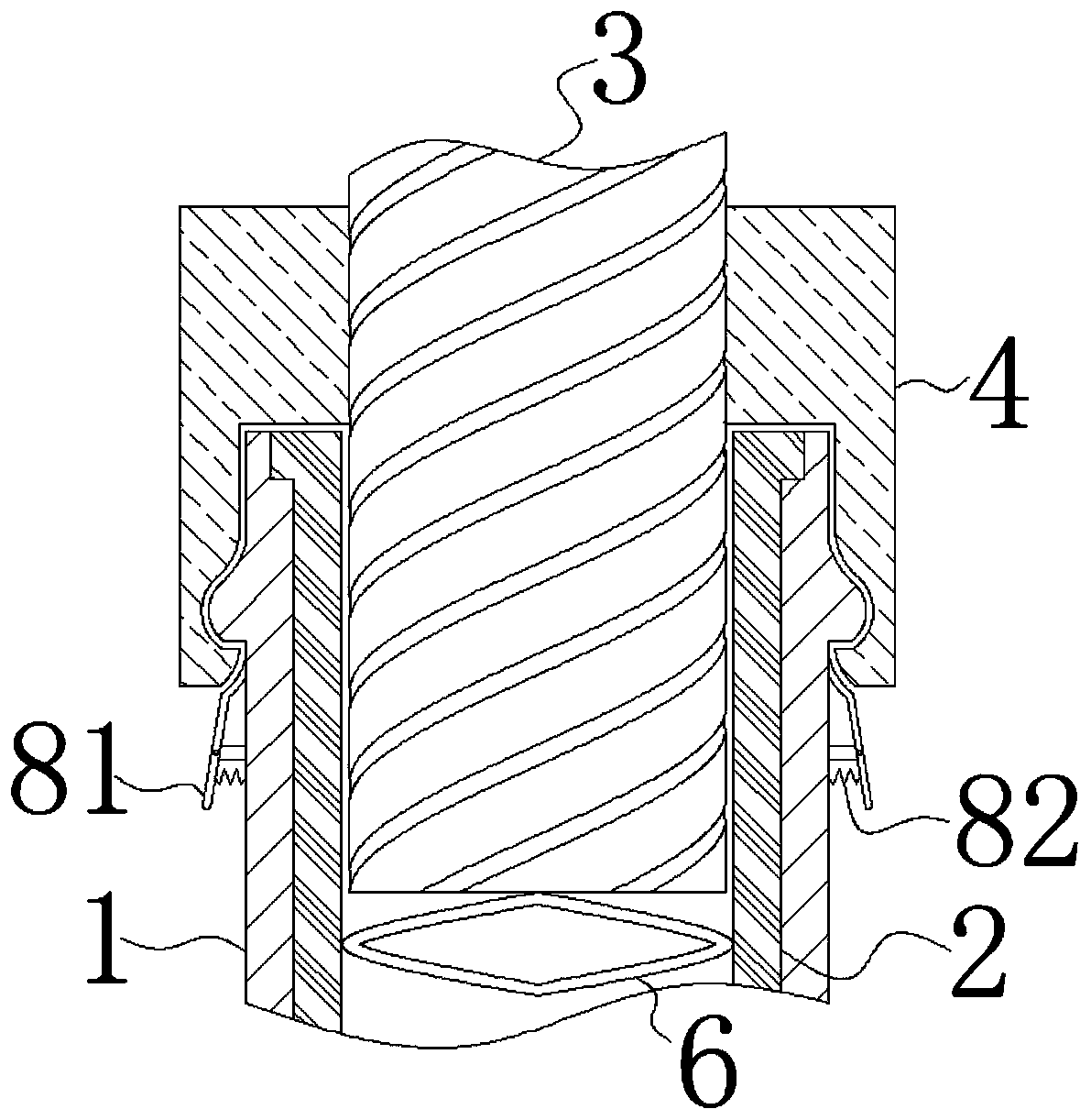
[0046] like Figure 1 to Figure 3 As shown, the needle tube includes an outer tube 1 and an inner tube 2 , and the inner tube 2 is sleeved in the outer tube 1 and can slide freely in the outer tube 1 . A second ejection device and a second fixing device 8 are arranged between the outer tube 1 and the inner tube 2 . The second ejection device includes a second spring 7 , and the second spring 7 is installed on the bottom of the outer tube 1 and the bottom outside of the inner tube 2 between. The second fixing device 8 includes a b button 81 and a b spring 82 . The middle of the b button 81 is hinged to the outer wall of the outer tube 1 through a column, and the b spring 82 is connected between one side of the b button 81 and the outer wall of the outer tube 1 . ...
PUM
 Abstract
Description
Claims
Application Information
 - R&D
- Intellectual Property
- Life Sciences
- Materials
- Tech Scout
- Unparalleled Data Quality
- Higher Quality Content
- 60% Fewer Hallucinations
Browse by: Latest US Patents, China's latest patents, Technical Efficacy Thesaurus, Application Domain, Technology Topic, Popular Technical Reports.
© 2025 PatSnap. All rights reserved.Legal|Privacy policy|Modern Slavery Act Transparency Statement|Sitemap|About US| Contact US: help@patsnap.com


