High-efficiency mesh drilling new method

A new method and drilling technology, applied in the direction of boring/drilling, drilling/drilling equipment, metal processing equipment, etc., can solve the difficulty of tool cooling, the chip blocking the drill chip flute, the easy skew of the drilling axis, etc. question

Inactive Publication Date: 2019-05-07
DALIAN UNIV
View PDF4 Cites 1 Cited by
  • Summary
  • Abstract
  • Description
  • Claims
  • Application Information

AI Technical Summary

Problems solved by technology

[0002] In machining, when drilling a hole with a small diameter and a large depth, especially when drilling a hole on a steel part, there are usually the following main problems: difficulty in chip removal, difficulty in tool cooling, and easy skewing of the drilling axis
Whether these problems can be properly solved is related to the quality and productivity of deep hole processing, processing accuracy and thermal deformation of the tool, etc., and may even make the processing impossible
For example, when drilling a deep mesh, if the chips cannot be discharged in time, the chips may be blocked in the chip flute of the drill bit, which will not only affect the machining accuracy, but also cause the drill bit to break
[0003] Due to the large number of holes that need to be drilled on the workpiece, it is very likely that the drill bit will wear out during the processing, and the drill bit will need to be replaced, or the processing may be stopped after get off work, and abnormal conditions such as power outages may occur during processing.

Method used


Image

  • High-efficiency mesh drilling new method
  • High-efficiency mesh drilling new method
  • High-efficiency mesh drilling new method

Examples


Embodiment 1

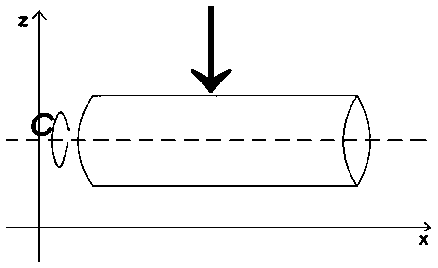
[0069] like Figure 1-3 As shown, this embodiment provides a new method for high-efficiency mesh drilling, the workpiece to be processed is cylindrical, and the specific steps include:

[0070] S1. The drill bit moves along the x-axis direction, the workpiece rotates around the central axis C-axis, the drill bit can be aligned with any hole in the same row on the workpiece; the drill bit moves along the z-axis, the workpiece can be drilled, or the drill bit can be withdrawn.

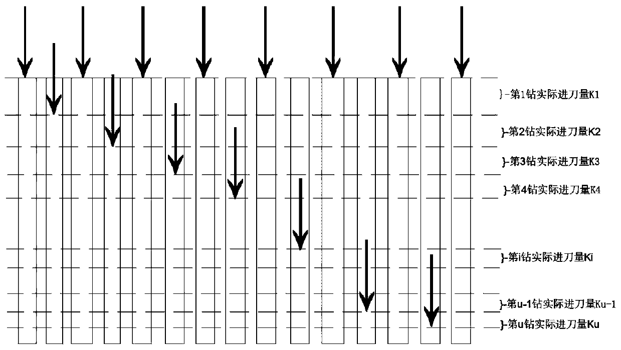
[0071] S2. Drill positioning hole: Drilling the positioning hole is to use a thinner drill bit to drill a hole with a depth of about 2mm at the position to be drilled on the surface of the unprocessed workpiece. The purpose of the positioning hole is to guide the main drill bit into the drilling position.

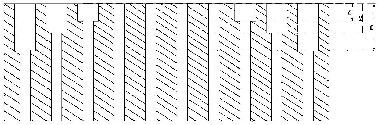
[0072] S3. Drilling the main hole: refers to the depth of the hole that needs to be drilled at each positioning hole position on the cylindrical workpiece by selecting a drill bit that meets the hole di...

Embodiment 2

[0110] The present embodiment provides a kind of algorithm step that runs in the machine when drilling the positioning hole as follows:

[0111] (1) The user presses the cycle start button;

[0112] (2) Move the x-axis, the C rotation axis and the z-axis, so that the drill bit starts to row the surface position of the starting hole;

[0113] (3) Prompt the user to adjust the drill fixture so that the user can accurately adjust the position of the drill after installing a new drill;

[0114] (4) The user presses the cycle start button, and the drill starts to rotate;

[0115] (5) The user confirms that the drill speed is normal, presses the cycle start button to start processing;

[0116] (6) If the number of initial rows is less than the number of terminated rows, or the number of initial rows is equal to the number of terminated rows and the number of initial holes is less than or equal to the number of terminated holes, then continue to step 7; otherwise, go to step 12; ...

Embodiment 3

[0125] The algorithm steps that run in the machine when drilling the main hole are as follows:

[0126] (1) The user presses the cycle start button;

[0127] (2) Move the x-axis, the C rotation axis and the z-axis, so that the drill bit starts to row the surface position of the starting hole;

[0128] (3) Prompt the user to adjust the drill fixture so that the user can accurately adjust the position of the drill after installing a new drill;

[0129] (4) The user presses the cycle start button, and the drill starts to rotate;

[0130] (5) The user confirms that the drill speed is normal, and presses the cycle start button to start processing;

[0131] (6) If the number of initial rows is less than the number of terminated rows, or the number of initial rows is equal to the number of terminated rows and the number of initial holes is less than or equal to the number of terminated holes, then continue to step 7; otherwise, go to step 14;

[0132] (7) Determine the z coordinat...


PUM


Abstract

The invention discloses a high-efficiency mesh drilling new method. A workpiece to be processed is cylindrical, the method has the specific steps that S1, drill bits are aligned with each row of holeson the cylinder workpiece; S2, location holes are drilled: a hole with a certain depth is drilled on the surface of an unmachined cylinder workpiece by using a drill bit; S3, a main hole is drilled:according to the machining requirements, the drill bit in line with the hole diameter is selected, and the required hole depth is machined at the position of each location hole on the cylinder workpiece; when a certain amount of feed is drilled, the drill bits need to be retired for chip removal, reception is conducted, and the drilling of the hole is completed; and S4, pressure-relief holes are drilled: the pressure-relief holes with a certain depth are drilled at both ends of the cylinder workpiece by using the drill bit that is thicker than the drill bit drilling the main hole, when the workpiece with thousands of holes needs to be machined for several days in a row, once shut down or unexpected power off happens, run and machine directly as long as restarted, and the hole machined lasttime is continued to be machined.

Description

technical field [0001] The invention relates to a new high-efficiency mesh drilling method, which is applied to mechanical processing in the field of equipment manufacturing such as automobiles, moulds, printing machinery, packaging machinery, food machinery, and aerospace. Background technique [0002] In machining, when drilling a hole with a small diameter and a large depth, especially when drilling a hole on a steel part, there are usually the following main problems: difficulty in chip removal, difficulty in tool cooling, and easy skewing of the drilling axis. Whether these problems can be properly solved is related to the quality and productivity of deep hole processing, processing accuracy and thermal deformation of the tool, etc., and may even make the processing impossible. For example, when drilling a deep mesh, if the chips cannot be discharged in time, the chips may be blocked in the chip flute of the drill bit, which will not only affect the machining accuracy, ...

Claims


Application Information

Patent Timeline
Patent Type & Authority Applications(China)
IPC IPC(8): B23B41/00
Inventor 甄恒洲王珍王元刚王建维
Owner DALIAN UNIV
Why Eureka
Try Eureka