Anti-pressure reinforcement device for wall sticking holding circular rods and reinforcement method
A reinforcement device and round rod technology, which is applied in construction, building structure, and building material processing, can solve the problems of adding rods, increasing steel consumption, and redundantly improving the bearing capacity of steel structures, so as to prevent bending Effects of deformation, increased strength, and reduced waste
- Summary
- Abstract
- Description
- Claims
- Application Information
AI Technical Summary
Problems solved by technology
Method used
Image
Examples
Embodiment 1
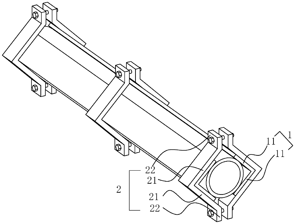
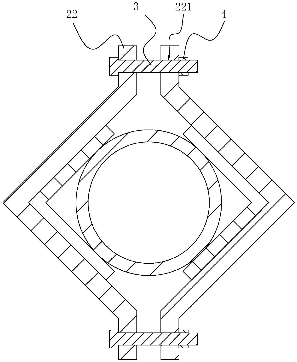
[0040] Embodiment 1: A kind of anti-compression strengthening device of wall-attached and embracing circular rods, see the attached figure 1 , including two reinforcements 1 attached to the outside of the rod and arranged symmetrically with respect to the axis of the rod, and several clamps attached to the side of the two reinforcements 1 away from the rod for fixing the reinforcement 1 on the rod 2. The reinforcement 1 includes two reinforcement plates 11 that are fixedly connected together, and the sides of the two reinforcement plates 11 that are close to each other are fixedly connected together, and the angle between the two reinforcement plates 11 is equal to 90°; two sets of fixtures 2, The two clamps 2 of the same group are respectively in contact with the sides of the two reinforcing plates 11 facing away from each other; the clamps 2 include two splints 21 fixedly connected together and two fixed plates 22 fixedly connected on the sides of the two splints 21 away from...
Embodiment 2
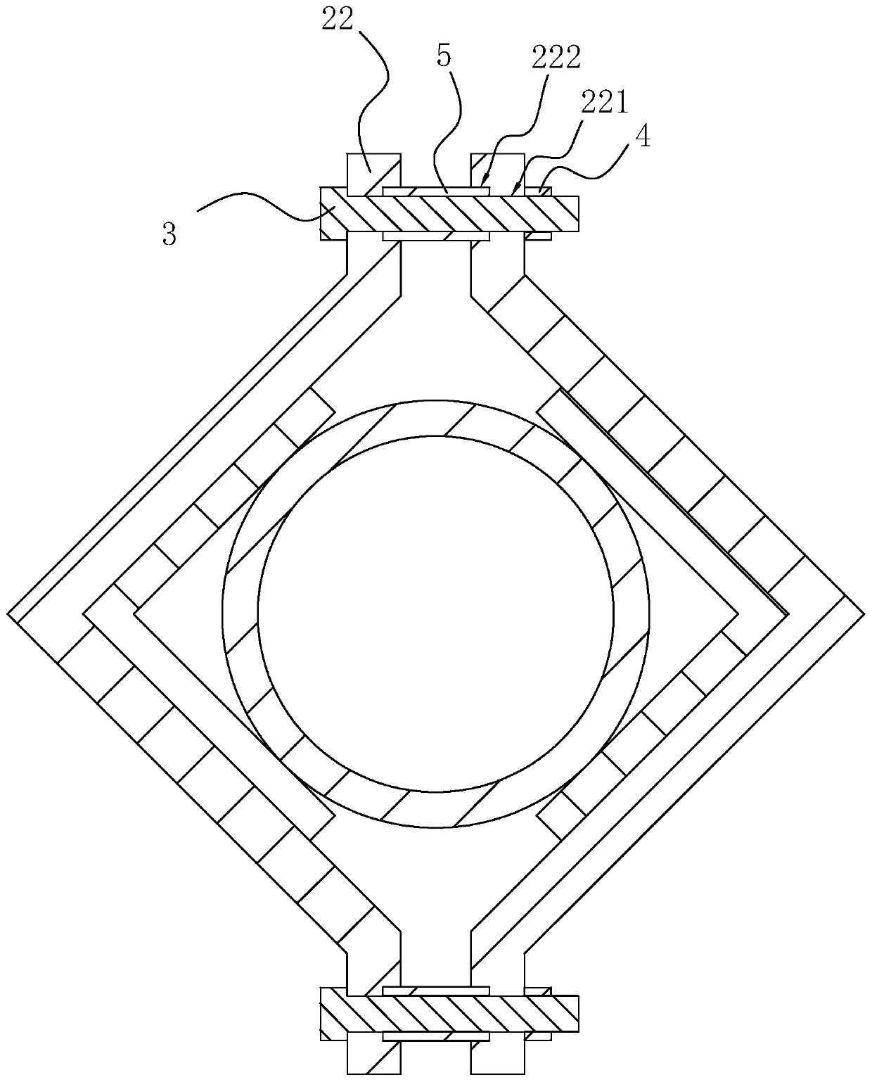
[0043] Embodiment 2: A wall-attached and embracing circular bar anti-compression reinforcement device. The difference between this embodiment and Embodiment 1 is that a reinforcing sleeve 5 is provided on the outer side of the fixing bolt 3, and the reinforcing sleeve 5 is located at the same Between the two fixed plates 22 corresponding to each other on the two clamps 2 of the same group, a limiting groove 222 is provided on the side where the two corresponding fixed plates 22 on the two clamps 2 of the same group are close to each other, and the limiting groove 222 is the same as the fixing hole 221. The shaft and the diameter of the limiting groove 222 are equal to the outer diameter of the reinforcement sleeve 5 . The inner diameter of the reinforcing sleeve 5 is equal to the diameter of the fixing bolt 3, and the strength of the fixing bolt 3 can be increased by arranging the reinforcing sleeve 5, so as to prevent the fixing bolt 3 from bending after being stressed.
Embodiment 3
[0044] Embodiment 3: A wall-attached embracing type circular bar anti-compression reinforcement device. The difference between this embodiment and Embodiment 1 is that there are several reinforcements 1, and several reinforcements 1 are divided into two groups. The two groups of reinforcements 1 are arranged symmetrically with respect to the axis of the rod, each group of reinforcements 1 are attached to each other, and the angle between the two reinforcement plates 11 of the reinforcement 1 faces one side of the axis of the rod. The inside of the clamp 2 is in contact with the outside of the outermost reinforcement 1 , so that the two sets of reinforcement 1 are fixed on the bar through the clamp 2 . The side of the reinforcement 1 close to the axis of the rod is fixedly connected with a mating block 111 whose length direction is parallel to the length of the reinforcement 1, and the side of the reinforcement 1 away from the axis of the rod is provided with a mating block 111 ...
PUM
 Abstract
Description
Claims
Application Information
 - R&D
- Intellectual Property
- Life Sciences
- Materials
- Tech Scout
- Unparalleled Data Quality
- Higher Quality Content
- 60% Fewer Hallucinations
Browse by: Latest US Patents, China's latest patents, Technical Efficacy Thesaurus, Application Domain, Technology Topic, Popular Technical Reports.
© 2025 PatSnap. All rights reserved.Legal|Privacy policy|Modern Slavery Act Transparency Statement|Sitemap|About US| Contact US: help@patsnap.com


