a wind wheel

The technology of a wind wheel and a wind wheel shaft is applied to the wind wheel. It can solve the problems of inability to measure and measure the accuracy of measurement, difficult to afford costs for small and medium-sized enterprises, and expensive bearings, so as to save costs, reduce rotational resistance, and reduce the impact of friction.

Active Publication Date: 2020-09-11
白士德(珠海)电子科技有限公司
View PDF9 Cites 0 Cited by
  • Summary
  • Abstract
  • Description
  • Claims
  • Application Information

AI Technical Summary

Problems solved by technology

[0003] The rotation of the existing wind wheel is affected by the structure and materials, it is difficult to start the rotation under the condition of low wind speed, and the wind speed can only be started at high speed. Under the condition of low speed, it cannot be measured or the measurement accuracy is low. One is to add two bearings to the wind wheel, so that the wind wheel can rotate at low wind speeds, but the price of the bearings is too expensive, and it is difficult for small, medium and micro enterprises to afford the cost

Method used


Image

  • a wind wheel
  • a wind wheel
  • a wind wheel

Examples


Embodiment Construction

[0027] A wind wheel of the present invention is illustrated in conjunction with the accompanying drawings

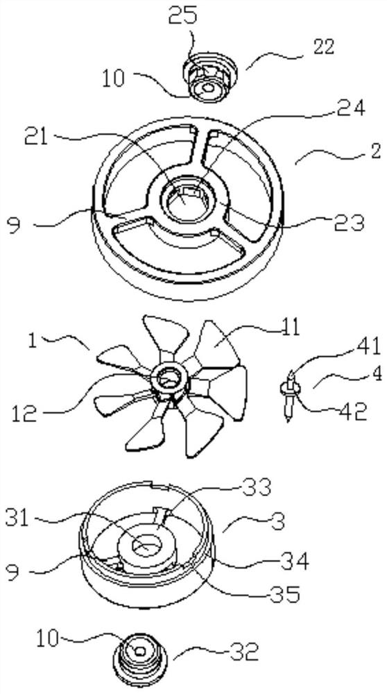
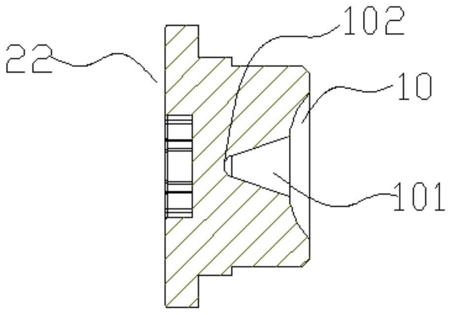
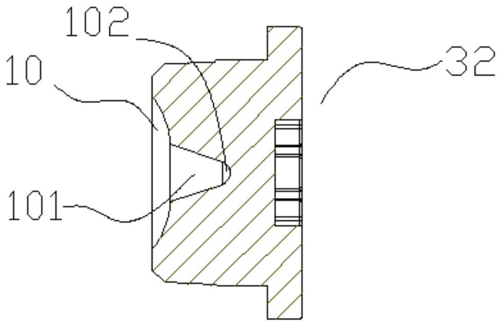
[0028] Such as Figure 1 to Figure 3 As shown, a wind wheel includes a wind wheel frame and a wind wheel blade 1, the wind wheel frame detachably clamps and fixes the wind wheel blade 1, and the wind wheel frame includes a wind wheel frame upper cover 2 and a wind wheel frame The lower cover 3, and the axes of the wind wheel frame upper cover 2 and the wind wheel frame lower cover 3 are respectively provided with a first hollow hole 21 and a second hollow hole 31 respectively corresponding to the first hollow hole 21 and the second hollow hole 31. The second hollow holes 31 are equipped with fittings, one side of the fittings is concave to form an arc portion 10, and the two fittings are installed on the upper cover 2 of the wind wheel frame and the lower cover 3 of the wind wheel frame Relatively fixed, the arc portion 10 is used to form a fixed area (not shown) locate...


PUM


Abstract

The invention discloses a wind wheel. The wind wheel comprises a wind wheel frame and wind wheel blades; the wind wheel frame comprises a wind wheel frame upper cover and a wind wheel frame lower cover, first hollow holes and second hollow holes which correspond to the wind wheel frame upper cover and the wind wheel frame lower cover are formed in the axes of the wind wheel frame upper cover and the wind wheel frame lower cover correspondingly, mounting parts are matched with the first hollow holes and the second hollow holes correspondingly, one sides of the mounting parts are downwards sunken to form arc-shaped parts, the two mounting parts are mounted on the wind wheel frame upper cover and the wind wheel frame lower cover and then relatively fixed, a fixed area located in the wind wheel is constituted through arc-shaped grooves, a wind wheel shaft is movably fixed in the fixed area, the two ends of the wind wheel shaft are conical tip ends and abut against the interior of the two arc-shaped grooves correspondingly. According to the wind wheel, an original wind wheel structure is improved, the two ends of the wind wheel shaft abut against the mounting parts, meanwhile, the two ends of the wind wheel shaft are each arranged to be in a conical shape, the resistance action applied to the wind wheel during application is relatively reduced, and using precision is improved.

Description

technical field [0001] The invention relates to the field of wind wheel measurement, in particular to a wind wheel. Background technique [0002] Wind wheel refers to the wind turbine component that converts wind energy into mechanical energy in electricity and energy science. Consists of blades and hub. When the fluid encounters a blocking surface at a certain angle to the flow direction, its dynamic pressure energy will form a force at a certain angle to the fluid flow direction on the blocking surface. When a group of blades with a certain angle to the flow direction are fixed on a rotating shaft to form a turbine (rotor, wind wheel), the turbine will obtain a rotational moment and rotate under the action of the fluid. [0003] The rotation of the existing wind wheel is affected by the structure and materials. It is difficult to start the rotation under the condition of low wind speed. One is to add two bearings to the wind rotor, so that the wind rotor can rotate at l...

Claims


Application Information

Patent Timeline
Patent Type & Authority Patents(China)
IPC IPC(8): G01P5/06F03D1/06F03D80/00
CPCY02E10/72
Inventor 白维
Owner 白士德(珠海)电子科技有限公司
Why Eureka
Try Eureka