Environment-friendly type aluminum scrap recycling melting furnace
An environmentally friendly, melting furnace technology, applied in furnaces, crucible furnaces, furnace types, etc., can solve the problems affecting the melting efficiency of aluminum scraps, uneven heat distribution, slow melting of aluminum scraps, etc., to improve melting efficiency and improve melting efficiency. , the effect of uniform texture
- Summary
- Abstract
- Description
- Claims
- Application Information
AI Technical Summary
Problems solved by technology
Method used
Image
Examples
Embodiment 1
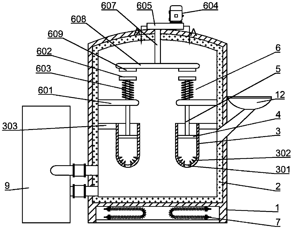
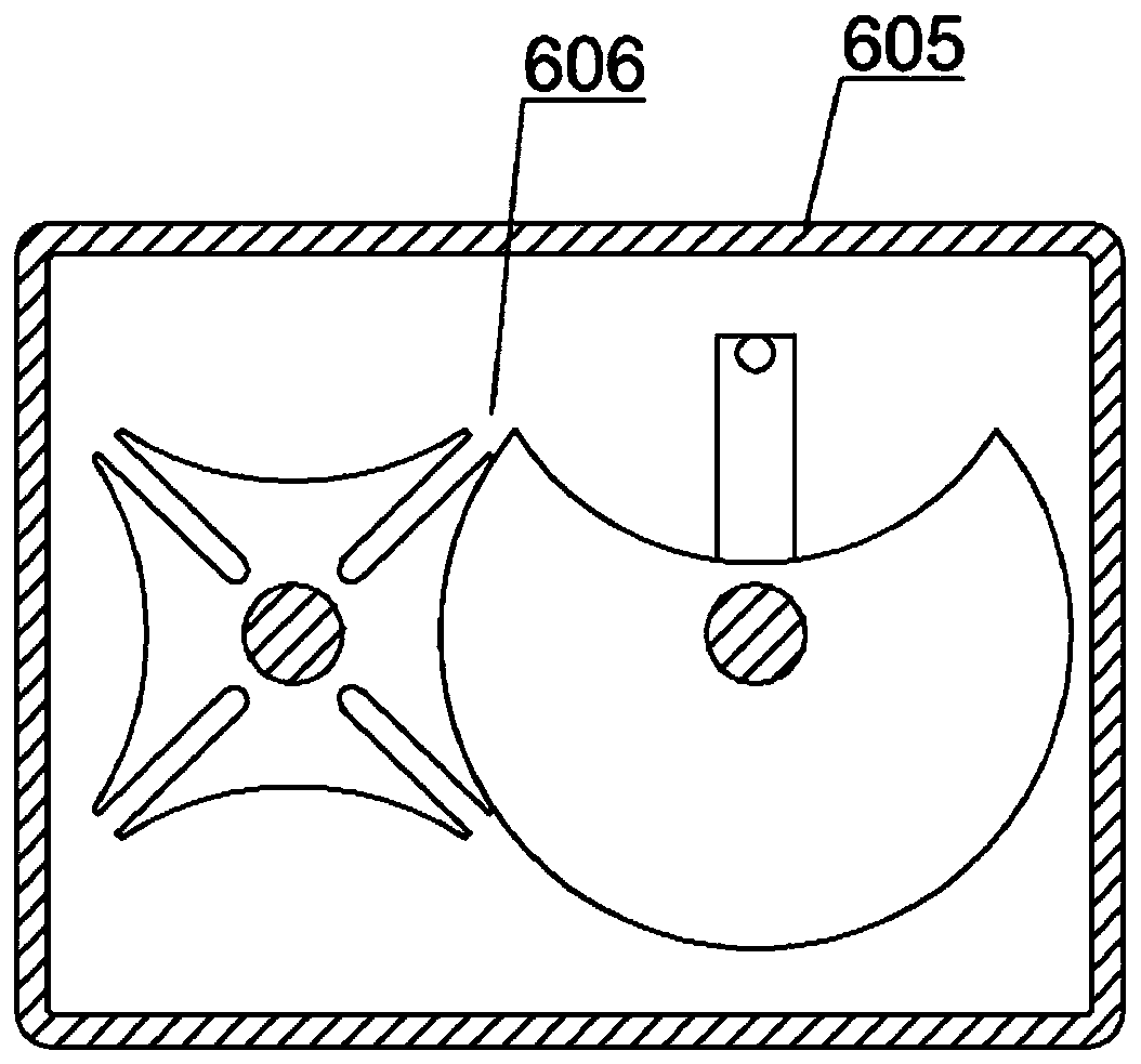
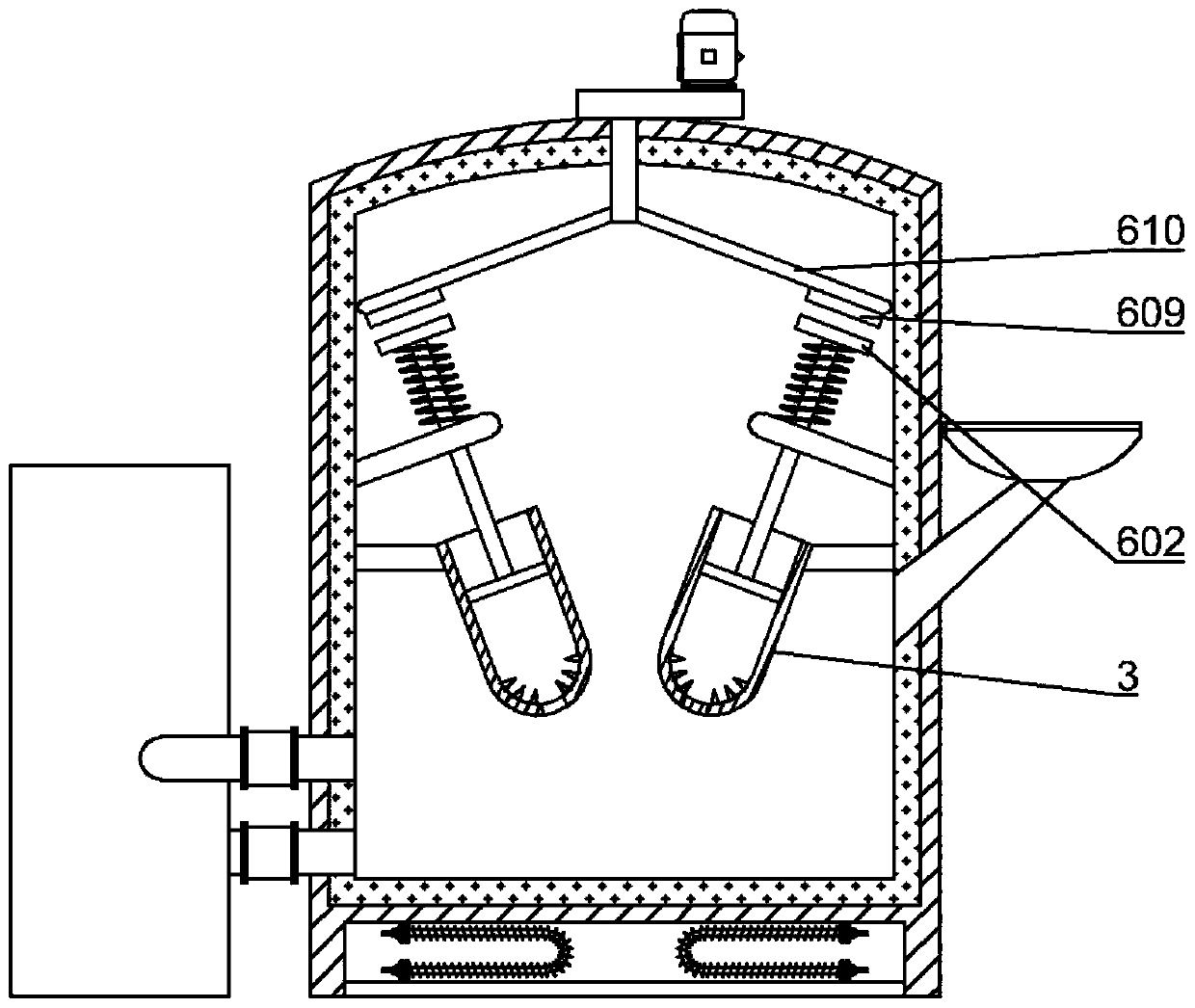
[0031] Such as figure 1 As shown, an environment-friendly aluminum chip recycling melting furnace includes a furnace body 1, a refractory lining 2 arranged on the inner wall of the furnace body 1, and a feeding funnel 12 with a cover connected to the side wall of the furnace body 1 and the heating device 7 installed at the bottom of the body of furnace 1; the aluminum chips are dropped into the body of furnace 1 through the feed funnel 12, and since the feed funnel 12 has a cover body, the inside of the body of furnace 1 is guaranteed to be in a sealed state, and the heating device 7. Heat the aluminum shavings in the furnace body 1 in a sealed state. Specifically, the heating device 7 can be an electric heating component or a combustible material to generate heat; but in the prior art, the molten liquid in the furnace body 1 is static , or as in figure 1 As shown, the molten liquid in the furnace body 1 also passes through the feed well 9 to realize the flow of the molten li...
Embodiment 2
[0039] like Figure 5 As shown, the only difference from Embodiment 1 is that the drive mechanism 6 includes a connecting rod 611 hinged to the top end of the elevating rod 5, the other end of the connecting rod 611 is hinged to the fixing member 615, and the upper part of the fixing member 615 is connected to There is a movable rod 614 extending from the top of the furnace body 1. A ceramic ring 616 is fixed through the upper side wall of the furnace body 1. The movable rod 614 passes through the ceramic ring 616. The ceramic ring 616 has a smooth surface and wear resistance, so that The movable rod 614 is more smooth when moving in the ceramic ring 616, and the movable rod 614 is connected with the reciprocating lifting mechanism installed on the furnace body 1. Specifically, the reciprocating lifting mechanism includes an electric telescopic rod 613 with a reciprocating movement function. The movable end of the rod 613 is connected with the movable rod 614, and the electric...
Embodiment 3
[0042] like Image 6 As shown, the only difference from Embodiment 2 is that the reciprocating lifting mechanism includes an impact plate 624 connected to the top end of the movable rod 614, and the impact plate 624 is connected to the furnace body 1 through a second elastic reset member 625. Preferably, The second elastic reset member 625 is a compression spring, and a speed reducer 622 is installed on the furnace body 1, and the output end of the second motor 621 is connected with the input end of the speed reducer 622, and the output end of the speed reducer 622 is connected with the impact plate 624 Cam 623 for striking;
[0043] The second motor 621 is started by an external switch, and the cam 623 continuously hits the impact plate 624 through the action of the speed reducer 622, so that the impact plate 624 moves up and down reciprocatingly, and the same working process of the embodiment 2 is realized, but Compared with Embodiments 1 and 2, this embodiment has the adva...
PUM
| Property | Measurement | Unit |
|---|---|---|
| Magnetic force | aaaaa | aaaaa |
Abstract
Description
Claims
Application Information
 - R&D
- Intellectual Property
- Life Sciences
- Materials
- Tech Scout
- Unparalleled Data Quality
- Higher Quality Content
- 60% Fewer Hallucinations
Browse by: Latest US Patents, China's latest patents, Technical Efficacy Thesaurus, Application Domain, Technology Topic, Popular Technical Reports.
© 2025 PatSnap. All rights reserved.Legal|Privacy policy|Modern Slavery Act Transparency Statement|Sitemap|About US| Contact US: help@patsnap.com


