
Method for multiplying integral time based on satellite dynamic time-varying whisk broom scanning

An integration time and satellite technology, which is applied in the field of satellite dynamic time-varying swing-sweep doubling integration time, can solve the problems of insufficient system energy, short imaging integration time, and large F-number of the optical system, so as to improve imaging quality and solve multi-level imaging Effects of insufficient energy or signal-to-noise ratio

Active Publication Date: 2019-05-07
CHANGCHUN INST OF OPTICS FINE MECHANICS & PHYSICS CHINESE ACAD OF SCI
View PDF4 Cites 2 Cited by
  • Summary
  • Abstract
  • Description
  • Claims
  • Application Information

AI Technical Summary

Problems solved by technology

Although the existing technology can improve the ground resolution by changing the internal parameter focal length of the space camera, for the conventional push-broom imaging method, increasing the focal length of the camera will cause the F number of the optical system to be too large and the imaging integration time to be short , the ground speed is too fast, the system energy is insufficient, and the imaging signal-to-noise ratio is severely reduced, etc.

Method used


Image

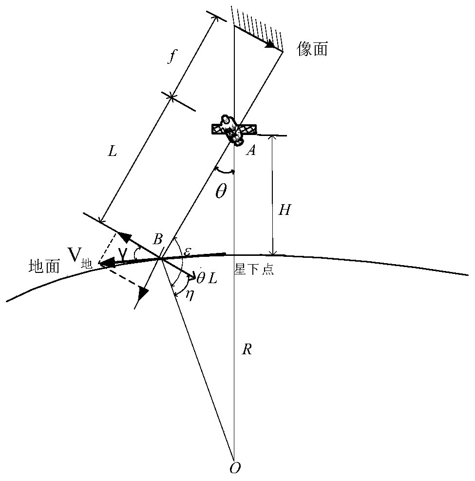
  • Method for multiplying integral time based on satellite dynamic time-varying whisk broom scanning
  • Method for multiplying integral time based on satellite dynamic time-varying whisk broom scanning
  • Method for multiplying integral time based on satellite dynamic time-varying whisk broom scanning

Examples


Embodiment Construction

[0017] The present invention will be described in further detail below in conjunction with the accompanying drawings and embodiments.

[0018] A method for doubling the integration time of satellite dynamic time-varying swing sweep, the method comprises the following steps:

[0019] 1. Determination of integration time for satellite conventional push-broom imaging

[0020] During the conventional satellite push-broom imaging scanning process, such as figure 1 As shown, the integration time of push-broom imaging satisfies the following relationship, and the ground target is taken as a sub-satellite point as an example.

[0021]

[0022] Among them, the speed of the satellite to the ground is as follows,

[0023]

[0024] After mapping the satellite's ground flight speed to the image plane, the moving speed of the satellite image plane can be obtained as follows,

[0025]

[0026] The radius of the earth is R=6371.393×10 3 , the mass of the earth is M=5.965×10 24 ,...


PUM


Abstract

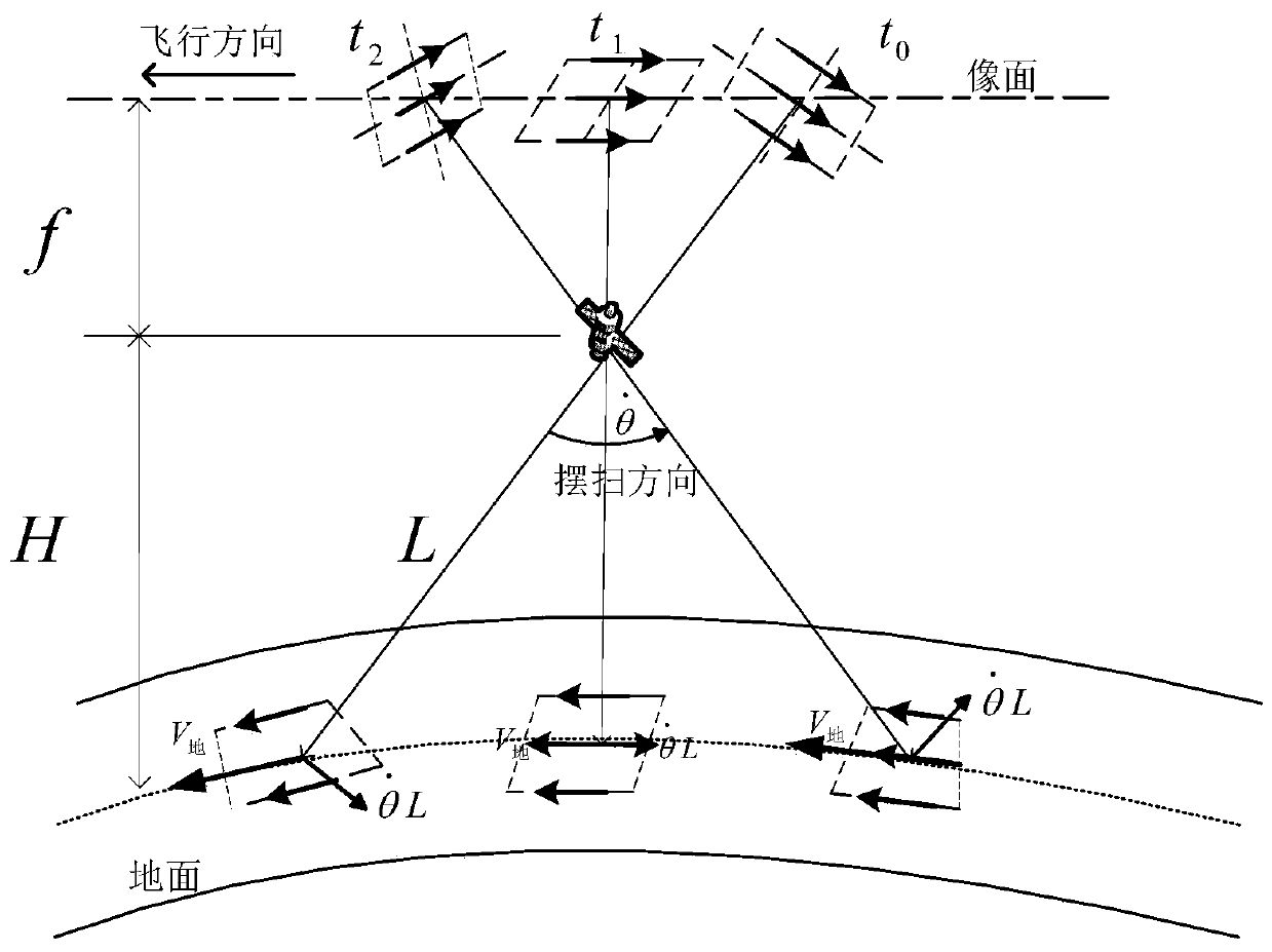
The invention discloses a method for multiplying integral time based on satellite dynamic time-varying whisk broom scanning, which relates to the field of space optical satellite dynamic imaging. Themethod comprises the following steps: pointing the pitch of a satellite to a certain angle; establishing an image plane moving speed vector model corresponding to multiple integral time; and calculating the dynamic maneuvering angular velocity of the satellite with multiple integral time under a certain pitch angle, so as to realize the dynamic and maneuverable reduction of the push broom scanningspeed of the satellite and the multiplier increase of the imaging integration time. The method greatly improves the imaging integration time in the conventional push broom scanning without changing the inherent optical parameters of a high-resolution camera. By establishing a functional relationship between the dynamic real-time shifting maneuver and the image shifting speed of push broom scanning of the satellite at different pitch angles, the real-time maneuvering speed reduction of the satellite attitude is achieved, and the push broom scanning speed of the image plane is reduced, the goalof increasing the imaging integration time of the camera and keeping it unchanged is achieved, the image quality of the camera is significantly improved.

Description

technical field [0001] The invention relates to the field of dynamic imaging of space optical satellites, in particular to a method for doubling integration time of dynamic time-varying swing sweeps of satellites. Background technique [0002] Since the development of space optical remote sensing, high-resolution imaging and high signal-to-noise ratio imaging have always been a contradiction. noise ratio. Although the existing technology can improve the ground resolution by changing the internal parameter focal length of the space camera, for the conventional push-broom imaging method, increasing the focal length of the camera will cause the F-number of the optical system to be too large and the imaging integration time to be short , the ground speed is too fast, the system energy is insufficient, and the imaging signal-to-noise ratio is severely reduced. Contents of the invention [0003] In order to solve the problems existing in the prior art, the present invention pr...

Claims


Application Information

Patent Timeline
Patent Type & Authority Applications(China)
IPC IPC(8): G01C11/00G01N21/01G01N21/17
Inventor 杨秀彬徐婷婷金光王家琪常琳
Owner CHANGCHUN INST OF OPTICS FINE MECHANICS & PHYSICS CHINESE ACAD OF SCI
Learn More