
a mems microphone

A microphone and sound hole technology, which is applied in the field of MEMS microphones, can solve problems such as product failure, rosin and other impurities entering the front sound cavity, and achieve the effect of improving sensitivity and signal-to-noise ratio

Active Publication Date: 2019-01-29
SHANDONG GETTOP ACOUSTIC
View PDF6 Cites 0 Cited by
  • Summary
  • Abstract
  • Description
  • Claims
  • Application Information

AI Technical Summary

Problems solved by technology

[0007] In view of this, the present application provides a MEMS microphone, which is used to solve the problem in the prior art that impurities such as rosin easily enter the front sound cavity during the reflow soldering process of the MEMS microphone, resulting in product failure.

Method used


Image

  • a mems microphone
  • a mems microphone
  • a mems microphone

Examples


Embodiment Construction

[0030] The following will clearly and completely describe the technical solutions in the embodiments of the present invention with reference to the accompanying drawings in the embodiments of the present invention. Obviously, the described embodiments are only some, not all, embodiments of the present invention. Based on the embodiments of the present invention, all other embodiments obtained by persons of ordinary skill in the art without making creative efforts belong to the protection scope of the present invention.

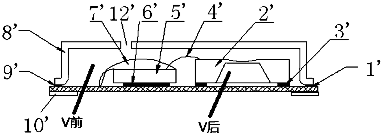
[0031] In order to solve the problem in the prior art that impurities such as rosin easily enter the front sound cavity through the sound hole in the process of reflow soldering, this application designs a MEMS microphone that can effectively prevent impurities such as rosin from entering the front or rear sound cavity of the MEMS microphone.

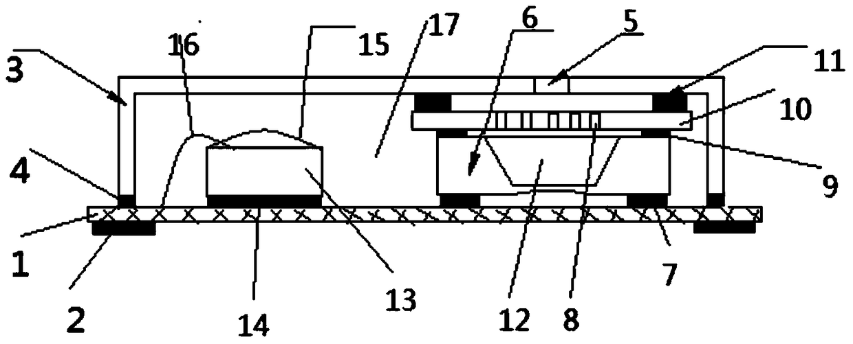
[0032] figure 2 For the structural diagram of a MEMS microphone disclosed in the embodiment of the present applicati...


PUM


Abstract

The invention discloses an MEMS (micro-electro-mechanical system) microphone. The MEMS microphone comprises a circuit board, a package structure enclosed by a housing, and a sound hole, wherein an EMS DIE sensor and an integrated circuit ASIC (application specific integrated circuit) chip which are fixed on the circuit board are arranged inside the package structure; the sound hole is formed in the housing; the open end of an inner cavity of the EMS DIE sensor faces towards one side of the sound hole; a sealed passage is formed between the sound hole and the open end of the inner cavity of the sensor. The sound hole of the MEMS microphone is formed in the housing so as to ensure that in a reflow soldering process, impurities cannot enter the cavity of the EMS DIE sensor; the MEMS DIE is inverted to enlarge a back cavity of a forward-sound MEMS MIC, so that the defects that the sensitivity and signal-noise ratio of a forward-sound MEMS MIC product are low due to too small back cavity are overcome and the sensitivity and the signal-noise ratio of the forward-sound product are effectively improved.

Description

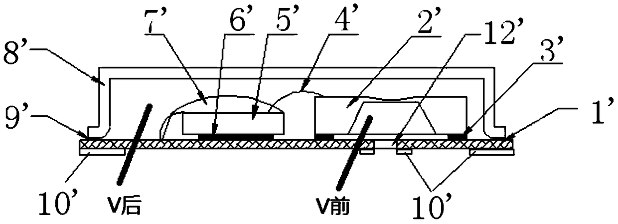
technical field [0001] The present application relates to the technical field of speaker equipment, and more specifically, relates to a MEMS microphone. Background technique [0002] A Micro-Electro-Mechanical System (MEMS) microphone is a microphone manufactured based on MEMS technology. [0003] The structure of the MEMS microphone in the prior art is usually as follows figure 1 As shown in ', it mainly includes: circuit board 1', MEMS DIE sensor 2', integrated circuit ASIC chip 5', and housing 8'; wherein the MEMS DIE sensor 2' is bonded to the circuit board 1' with bottom glue 3' Above, the integrated circuit ASIC (Application Specific Integrated Circuit) chip 5' is fixed on the circuit board 1' with bottom glue 6', and the shell 8' is fixed on the circuit board 1' with solder paste or glue 9' , the MEMS DIE sensor 2' is connected with the integrated circuit ASIC chip 5' and the circuit board 1' through a gold wire 4', wherein "V rear" is the rear sound cavity and "V f...

Claims


Application Information

Patent Timeline
Patent Type & Authority Patents(China)
IPC IPC(8): H04R19/04
Inventor 侯杰
Owner SHANDONG GETTOP ACOUSTIC
Learn More