Pulse laser signal-to-noise ratio detection device
What is Al technical title?
Al technical title is built by PatSnap Al team. It summarizes the technical point description of the patent document.
A pulsed laser and detection device technology, applied in the direction of instruments, etc., can solve the problem that the detection range of signal-to-noise ratio cannot exceed 30dB, and achieve the effects of large dynamic detection range, accurate and reliable processing, and high signal-to-noise ratio
Active Publication Date: 2019-06-18
SHANGHAI INST OF OPTICS & FINE MECHANICS CHINESE ACAD OF SCI
View PDF7 Cites 0 Cited by
Summary
Abstract
Description
Claims
Application Information
AI Technical Summary
This helps you quickly interpret patents by identifying the three key elements:
Problems solved by technology
Method used
Benefits of technology
Problems solved by technology
The US patent can detect the signal-to-noise ratio of a known continuous pulse, but the detection range of the signal-to-noise ratio cannot exceed 30dB, because when the signal light is directly sent to the photodetector, the signal light is very close to what the photodetector can detect the saturation of
Method used
Image
Click on the blue label to locate the original text in one second.
Reading with bidirectional positioning of images and text.
Examples
Embodiment Construction
[0032] The present invention will be described in detail below in conjunction with the accompanying drawings and embodiments. This embodiment is carried out on the premise of the technical solution of the present invention, and detailed implementation and specific operation process are given, but the protection scope of the present invention is not limited to the following embodiments.
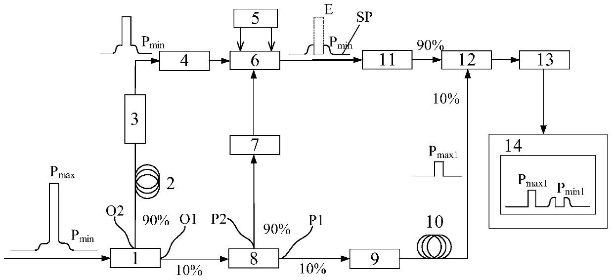
[0033] figure 1 It is a structural schematic diagram of the pulse laser signal-to-noise ratio detection device of the present invention, and the pulse laser signal-to-noise ratio detection device of the present invention is used to detect the signal-to-noise ratio of a nanosecond-level single pulse laser signal. The following is an embodiment of the pulse laser signal-to-noise ratio detection device of the present invention.
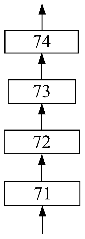
[0034] In this embodiment, a first optical fiber splitter 1, a delay optical fiber 2, an adjustable delayer 3, a polarization controller 4, a pulse bias generator 5, a ...
PUM
Abstract
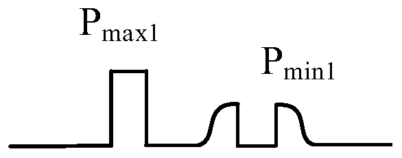
Disclosed is a pulse laser signal-to-noise ratio detection device, which includes a first fiber optic splitter, a delay fiber, an adjustable delayer, a polarization controller, a pulse bias generator,a dual-stage electrooptic intensity modulator, a second fiber optic splitter, a trigger unit, an attenuation device, a delay device, a signal gain device, a multi-optical path multiplexing device, aphotoelectric detection device, an electric signal processing device and the like. The pulse laser signal-to-noise ratio detection device in the invention detects the background noise intensity of thelaser output pulse by using the first fiber optic splitter, the delay fiber, the adjustable delayer, the polarization controller, the pulse bias generator, the dual-stage intensity modulator, the second fiber optic splitter, the trigger unit and the signal gain device, detects the signal intensity of the main peak of the pulse at the same time by using the first fiber optic splitter, the second fiber optic splitter, the attenuation device and the delay device, and obtains the signal-to-noise ratio. The detection range of the signal-to-noise ratio of the device can reach 50dB with an accuracyof 1dB. The device has the characteristics of easy operation, high test accuracy, good reliability and the like.
Description
technical field [0001] The invention belongs to pulse laser technology, in particular to a pulse laser signal-to-noise ratio detection device, which is mainly used for processing optical pulse signals to detect the main peak and background noise intensity of the laser pulse signal, and obtain the signal-to-noise ratio. The invention is especially suitable for detecting the signal-to-noise ratio of a nanosecond single-pulse laser signal with a large dynamic range. Background technique [0002] Pulse lasers mainly include solid-state lasers and fiber lasers. The signal-to-noise ratio is an important technical indicator, which reflects the technical level of the laser system. At present, there are two main detection methods for the signal-to-noise ratio of nanosecond-level pulsed lasers: one is to use high-speed oscilloscopes and photodiodes for direct detection of photoelectric signal conversion, and the detection range can reach about ten dB; the other is to use multiple opti...
Claims
Application Information
Patent Timeline
Application Date:The date an application was filed.
Publication Date:The date a patent or application was officially published.
First Publication Date:The earliest publication date of a patent with the same application number.
Issue Date:Publication date of the patent grant document.
PCT Entry Date:The Entry date of PCT National Phase.
Estimated Expiry Date:The statutory expiry date of a patent right according to the Patent Law, and it is the longest term of protection that the patent right can achieve without the termination of the patent right due to other reasons(Term extension factor has been taken into account ).
Invalid Date:Actual expiry date is based on effective date or publication date of legal transaction data of invalid patent.
Patent Type & Authority Patents(China)
IPC IPC(8): G01J11/00
CPCG01J11/00
Inventor 范薇夏刚汪小超黄大杰郭江涛
Owner SHANGHAI INST OF OPTICS & FINE MECHANICS CHINESE ACAD OF SCI