Wave-front aberration detection device based on transverse shearing interference for beam expanding collimation system

A technology of wavefront aberration and transverse shearing, which is applied in the field of optical detection, can solve the problems of difficult processing, difficulty in measuring light beams, and high cost, and achieve the effects of large dynamic detection range, high detection sensitivity, and improved detection accuracy

Active Publication Date: 2013-07-17
BEIJING INSTITUTE OF TECHNOLOGYGY
View PDF4 Cites 0 Cited by
  • Summary
  • Abstract
  • Description
  • Claims
  • Application Information

AI Technical Summary

Problems solved by technology

However, there are deficiencies in the above two methods. For the Hartmann method: on the one hand, because it uses an array aperture with a lower wave surface sampling capability to sample the wave surface, it affects the detection accuracy of the wave surface to be measured; on the other hand, due to the The Mann plate is difficult to manufacture, and the processing technology limits the size of the Hartmann plate, making it difficult to measure beams with larger apertures
For the pentaprism scanning method: it is essentially a serial Hartmann method, which scans the entire light wave surface to be measured by a pentaprism to detect the wave surface to be tested; due to the surface error and angle manufacturing error of the pentaprism, the measured The wave surface will affect the detection accuracy of the wave surface to be tested. Therefore, the processing requirements for the pentaprism are very high, resulting in difficult processing and high cost.

Method used


Image

  • Wave-front aberration detection device based on transverse shearing interference for beam expanding collimation system
  • Wave-front aberration detection device based on transverse shearing interference for beam expanding collimation system
  • Wave-front aberration detection device based on transverse shearing interference for beam expanding collimation system

Examples


Embodiment Construction

[0025] The present invention will be described in further detail below in conjunction with the accompanying drawings and specific embodiments.

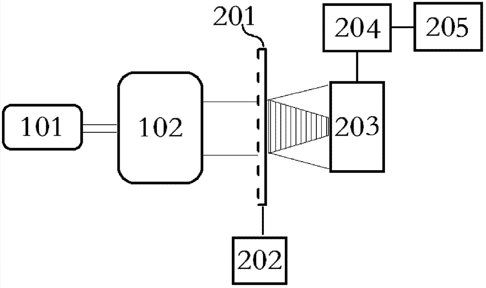
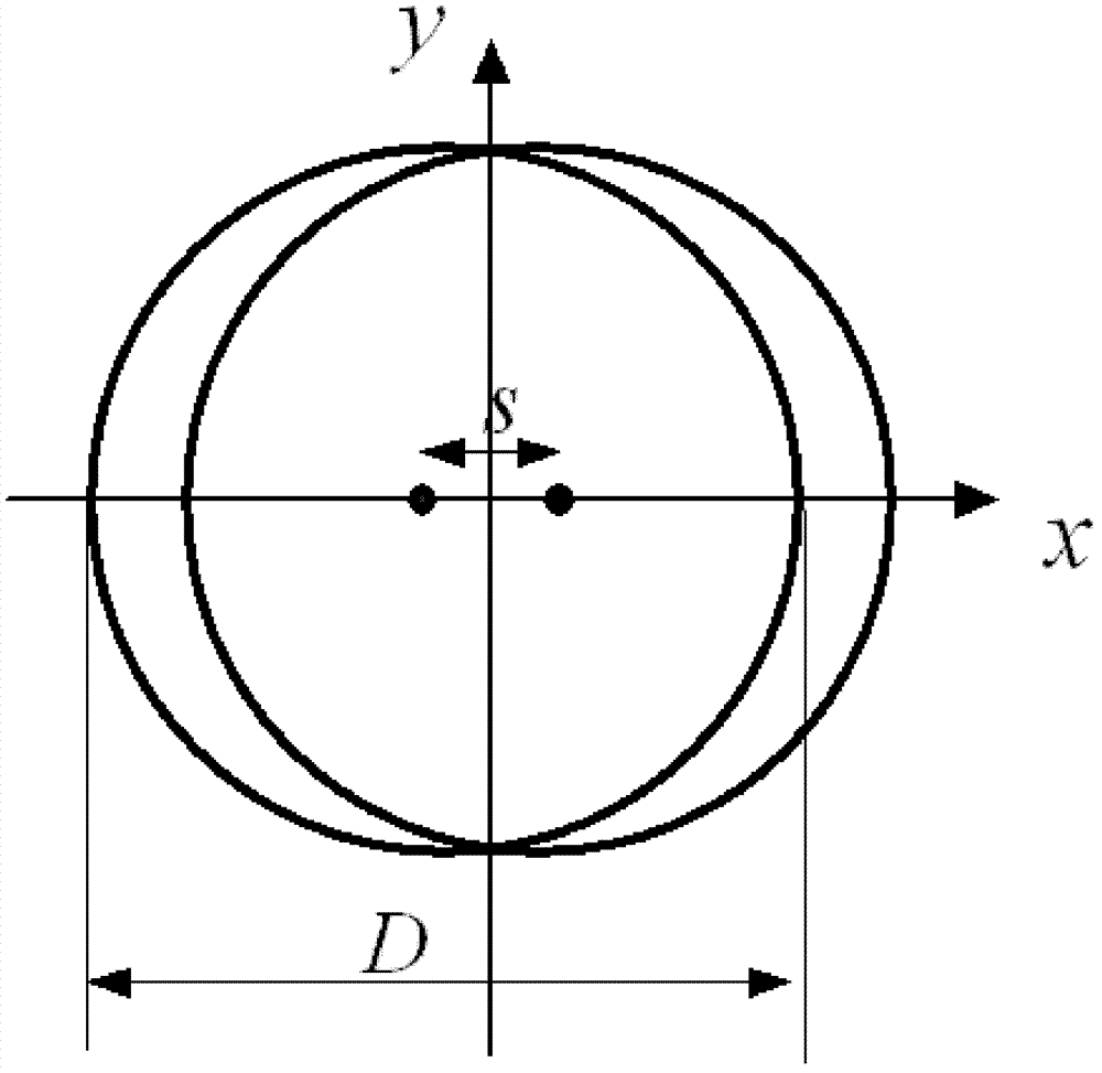
[0026] First, set the propagation direction of the outgoing beam of the beam expander collimator system as the z-axis, and establish a left-handed coordinate system with the z-axis, then the horizontal direction is the x-axis, and the vertical direction is the y-axis. The present invention is a wavefront aberration detection device for a beam expander collimation system based on transverse shear interference, such as figure 1 As shown, it includes a one-dimensional phase grating 201, an adjustment unit 202, a photodetection unit 203, a storage unit 204, and a signal processing unit 205; wherein, the one-dimensional phase grating 201 and the photodetection unit 203 are sequentially arranged on the outgoing beam of the beam expander collimation system on the optical path, and the one-dimensional phase grating 201 is located between the ...


PUM


Abstract

The invention provides a wave-front aberration detection device based on transverse shearing interference for a beam expanding collimation system. The device comprises a one-dimensional phase grating, an adjusting unit, a photoelectric detection unit, a storage unit and a signal processing unit, wherein the one-dimensional phase grating and the photoelectric detection unit are arranged on a lightbeam emitting optical path of the beam expanding collimation system in sequence; the one-dimensional phase grating is positioned between the beam expanding collimation system and the photoelectric detection unit; the width of a light-proof part between two adjacent non-light tight parts is p/6; the width of a non-light tight part is p/3; p is the period of the one-dimensional phase grating; p is set to be more than or equal to 16beta; and beta is the pixel size of the photoelectric detection unit. Due to the adoption of the detection device, the influences of multiple diffraction light of level +/-3 and over level +/-3 can be eliminated, the energy of formed interference wave light is mainly concentrated in diffraction light waves of level +/-1, the influences of other multiple diffraction light waves on wave-front aberration detection are eliminated, and the detection accuracy is increased.

Description

technical field [0001] The invention belongs to the technical field of optical detection, and in particular relates to a wavefront aberration detection device for a beam expander collimation system based on transverse shear interference. Background technique [0002] Although the beam emitted by the laser has good directionality, it still has a certain divergence angle. At present, the beam expander collimation system is usually used to improve its directionality, that is, the beam expander collimator system is set on the optical path of the laser, and the divergence angle of the beam emitted by the laser is compressed and the beam size is expanded. This process is called laser beam The expanded beam collimation. Beam expansion and collimation of laser beams are widely used in optical precision measurement and optical imaging. In terms of optical imaging, laser beam expansion and collimation is an important technology in laser direct writing lithography. After the laser be...

Claims


Application Information

Patent Timeline
Patent Type & Authority Patents(China)
IPC IPC(8): G01J9/02
Inventor 李艳秋汪海刘克
Owner BEIJING INSTITUTE OF TECHNOLOGYGY
Why Eureka
Try Eureka