
Damping shock absorber, as well as toolbar and tool with same applied
A shock absorber and damping technology, which is applied in the field of cutting processing, can solve the problems of not very obvious positive effect and limited application range, etc., and achieve the effects of good vibration reduction effect, high rigidity, and increased natural frequency
- Summary
- Abstract
- Description
- Claims
- Application Information
AI Technical Summary
Problems solved by technology
Method used
Image

Examples
Embodiment 1
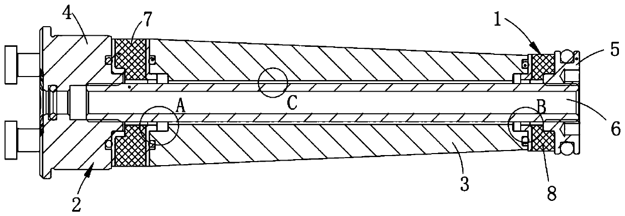
[0045] Such as figure 1 As shown, a damping shock absorber includes:
[0046] Adjustment lever 6;
[0047] A mass block 3, the mass block 3 is sheathed on the outside of the adjustment rod 6 through clearance fit;
[0048] A support block assembly 2, the two ends of the support block assembly 2 and the adjustment rod 6 are respectively connected by threaded fit;
[0049] The elastic body assembly 1 is sleeved on the outside of the adjustment rod 6 and placed between the mass block 3 and the support block assembly 2 .
[0050] The support block assembly 2, the elastic body assembly 1, and the mass block 3 are sealed and connected, and the gap between the mass block 3 and the adjustment rod 6 is filled with damping oil.
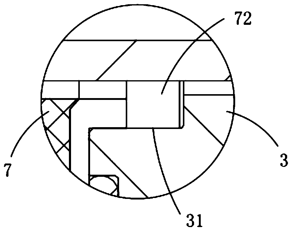
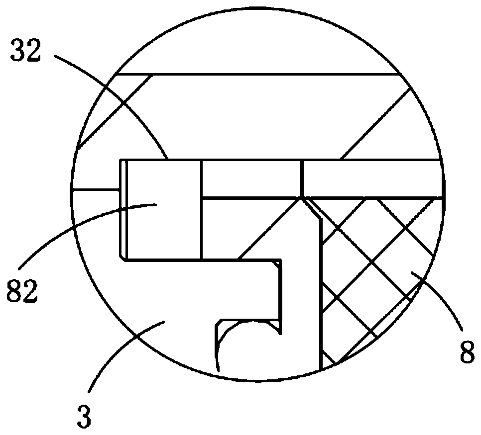
[0051] In this embodiment, the molded casing is stepped-fitted between the support block assembly and the elastic body assembly, thereby achieving greater shock absorption effects in both the axial and radial directions of the tool holder.
[0052] further,...
Embodiment 2
[0062] Such as Figure 7 As shown, the components that are the same as or corresponding to those in the first embodiment are marked with the corresponding reference numerals in the first embodiment. For the sake of simplicity, only the differences from the first embodiment will be described below. The difference between this embodiment two and embodiment one is:
[0063] This embodiment also discloses a damping and damping tool holder, which includes a tool holder body 9 and a damping and vibration absorber described in Embodiment 1, which is built into the body of the cutter holder 9 Inside, the inner wall of the cutter bar body 9 is provided with a cylindrical hole a91, a conical hole 92, a cylindrical hole b93 and a cylindrical hole c94 in sequence along its axial direction from front to back, and the cylindrical hole a91 is connected to the front end support block 4 It cooperates with the front elastic body 7 , the conical hole 92 cooperates with the mass block 3 , and th...
Embodiment 3
[0069] Such as Figure 8 As shown, the components that are the same as or corresponding to those in the first embodiment are marked with the corresponding reference numerals in the first embodiment. For the sake of simplicity, only the differences from the first embodiment will be described below. The difference between this embodiment three and embodiment one is:
[0070] This embodiment also discloses a damping and vibration-damping cutter, including a cutter head 10 and a damping and vibration-damping cutter bar described in Embodiment 2. The cutter head 10 is installed on the front end support block 4, It is fixed with the hollow structure front end of cutter bar body 9 simultaneously.
[0071] In this embodiment, the cutter head 10 is installed on the cutter bar of the second embodiment, and the vibration of the cutter head 10 is weakened during actual use, so as to improve the accuracy of the cutter work.
PUM
 Abstract
Description
Claims
Application Information