Eureka AIR delivers breakthrough ideas for toughest innovation challenges, trusted by R&D personnel around the world.

Omni-directional mechanical arm for laser welding

A laser welding and all-round technology, applied in the field of manipulators, can solve problems such as threats to the firmness of the welding head and fixed furniture, and the impact of the accuracy of the laser welding arm

Inactive Publication Date: 2019-05-10
朱金芝
View PDF0 Cites 4 Cited by
  • Summary
  • Abstract
  • Description
  • Claims
  • Application Information

AI Technical Summary

Problems solved by technology

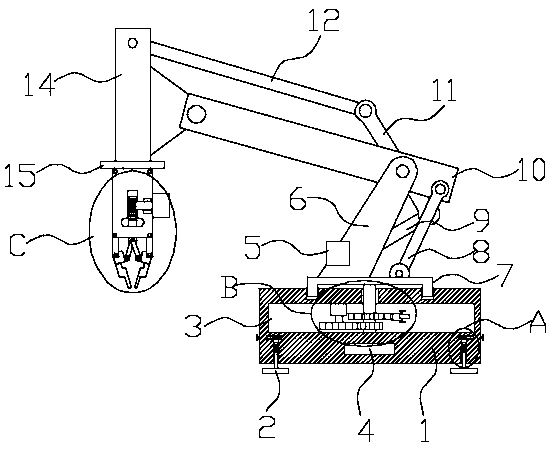
[0004] The purpose of the present invention is in order to solve the shortcoming that exists in the prior art, and proposes a kind of omni-directional manipulator for laser welding, it solves the problem that the existing manipulator for laser welding proposed in the above-mentioned background technology is because the welding head is in welding During the process, a certain impact force will be generated between the welding material and the welding workpiece during the melting process, which will pose a threat to the firmness between the welding head and the fixed furniture, thereby adjusting the distance between the welding head and the welding workpiece. Adjustment, and because the welding robot arm cannot adjust its welding height and the distance between it and the welding workpiece according to the size of the welding workpiece, which affects the welding accuracy of the laser welding arm

Method used


Image

  • Omni-directional mechanical arm for laser welding
  • Omni-directional mechanical arm for laser welding
  • Omni-directional mechanical arm for laser welding

Examples


Embodiment Construction

[0024] In order to make the above objects, features and advantages of the present invention more comprehensible, specific implementations of the present invention will be described in detail below in conjunction with the accompanying drawings. In the following description, numerous specific details are set forth in order to provide a thorough understanding of the present invention. However, the present invention can be implemented in many other ways different from those described here, and those skilled in the art can make similar improvements without departing from the connotation of the present invention, so the present invention is not limited by the specific implementations disclosed below.

[0025] It should be noted that when an element is referred to as being “fixed” to another element, it can be directly on the other element or there can also be an intervening element. When an element is referred to as being "connected to" another element, it can be directly connected ...


PUM


Abstract

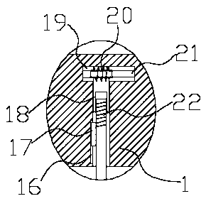
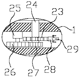
The invention discloses an omni-directional mechanical arm for laser welding. The omni-directional mechanical arm for the laser welding comprises a base, a first device cavity is formed inside the base, a horizontal steering device is arranged in the first device cavity, a rotating disc is arranged at the upper end of the horizontal steering device, a supporting arm is fixedly connected to the upper end of the rotating disc, and the upper end of the rotating disc is rotationally connected with a first connecting rod. According to the omni-directional mechanical arm for the laser welding, the problems that when a mechanical arm for the laser welding is used in a welding process, certain impact force can be generated between welding materials and welding workpieces in a melting process, which threaten firmness performance between a welding head and fixing clamps, so that the distance between the welding head and the welding workpieces have to be adjusted, and that as the welding mechanical arm cannot adjust the welding height of the welding mechanical arm and the distance between the welding mechanical arm and the welding workpieces according to the volume of the welding workpieces,so that welding accuracy of the laser welding arm is affected are all solved.

Description

technical field [0001] The invention relates to the technical field of manipulators, in particular to an omnidirectional manipulator for laser welding. Background technique [0002] Laser welding is an efficient and precise welding method that uses a high-energy-density laser beam as a heat source; laser welding is one of the important aspects of the application of laser material processing technology; the welding process is heat conduction, that is, the laser radiation heats the surface of the workpiece, and the surface heat passes through Heat conduction diffuses to the inside, and by controlling parameters such as the width, energy, peak power and repetition frequency of the laser pulse, the workpiece is melted to form a specific molten pool; with the continuous development of science and technology, the fields of laser welding are also constantly changing. Expanding, so as to design and innovate the robotic arm for laser welding, which will promote the development of las...

Claims


Application Information

Patent Timeline
IPC IPC(8): B25J9/04B25J9/10B25J19/00
Inventor 朱金芝
Owner 朱金芝
Why Eureka
Eureka Blog
Learn More