
Emergency braking auxiliary device and method for pneumatic brake

An emergency braking and auxiliary device technology, applied in the direction of braking transmission, braking, transportation and packaging, can solve the problems of engine power consumption, slow braking response, large energy consumption, etc., to reduce braking distance, The effect of speeding up the return of the piston and reducing the delay

Inactive Publication Date: 2019-05-10
JIANGSU UNIV
View PDF8 Cites 0 Cited by
  • Summary
  • Abstract
  • Description
  • Claims
  • Application Information

AI Technical Summary

Problems solved by technology

At the same time, it also has corresponding disadvantages, there are two main ones: 1 Brake response is slower than hydraulic brake system
2 It needs to consume the power of the engine, and the energy consumption is high
Due to the slow response of the air brake system, its emergency braking effect is relatively poor
In order to strengthen the emergency braking capability of the pneumatic brake system, patent application No. 201510846239.5 uses the air storage tank of the pneumatic brake as the power source and uses the negative pressure generated by the vacuum suction cup to assist emergency braking. Although the emergency braking capability is improved, its structure is complicated , higher energy consumption
Also as described in the patent application number 201720389166.6, during emergency braking, by making the suction cup on the vehicle absorb the ground to assist braking, the auxiliary effect is poor, the structure is complex and the energy consumption is high

Method used


Image

  • Emergency braking auxiliary device and method for pneumatic brake
  • Emergency braking auxiliary device and method for pneumatic brake
  • Emergency braking auxiliary device and method for pneumatic brake

Examples


Embodiment approach

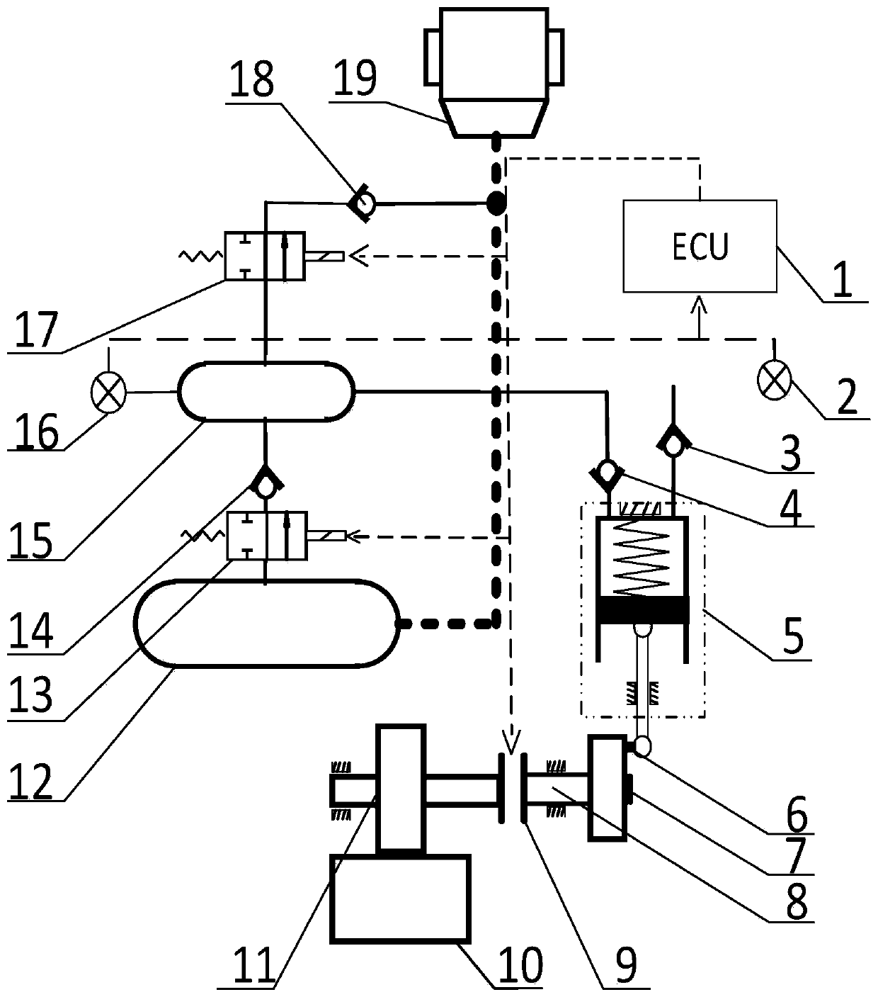
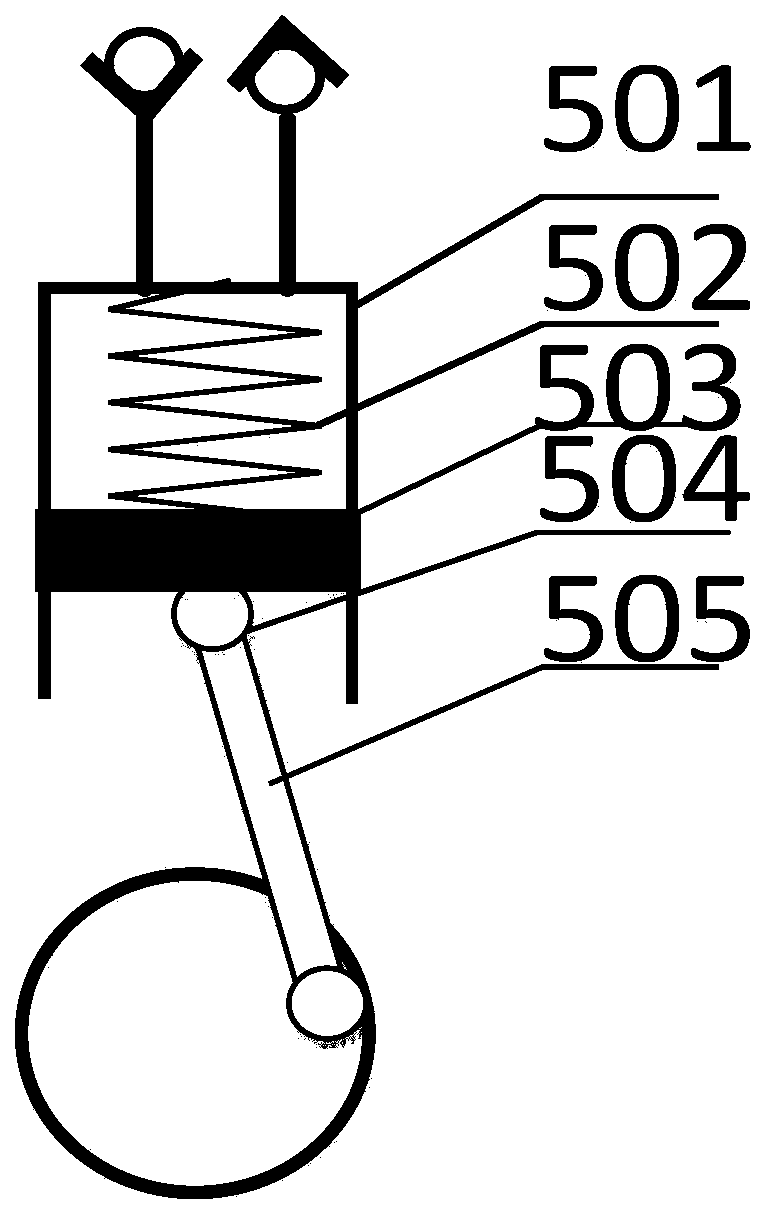
[0045] Such as figure 1 Shown is an embodiment of the air brake emergency braking auxiliary device of the present invention, and the air pressure brake emergency braking auxiliary device includes a first air storage tank 15, an energy conversion mechanism, a detection mechanism and an ECU1.

[0046]The first air storage tank 15 is used to connect with the brake air chamber 19 , and the pipeline connecting the first air storage tank 15 and the brake air chamber 19 is provided with a solenoid valve b17 and a one-way valve d18 . One end of the energy conversion mechanism is used to connect with the power output shaft, and the other end is connected to the second gas storage tank 15 to convert mechanical energy into air pressure internal energy; the detection mechanism is used to detect the stroke s and The air pressure p of the first air storage tank 15 ; the ECU1 is respectively connected with the detection mechanism, the energy conversion mechanism and the electromagnetic valve...

Embodiment 2

[0060] A vehicle includes the air brake emergency braking auxiliary device described in Embodiment 1, so it has the beneficial effects described in Embodiment 1, and will not be repeated here.

Embodiment 3

[0062] like Figure 7 As shown, a method for controlling the emergency braking auxiliary device of the air brake according to Embodiment 1 includes the following emergency braking control steps:

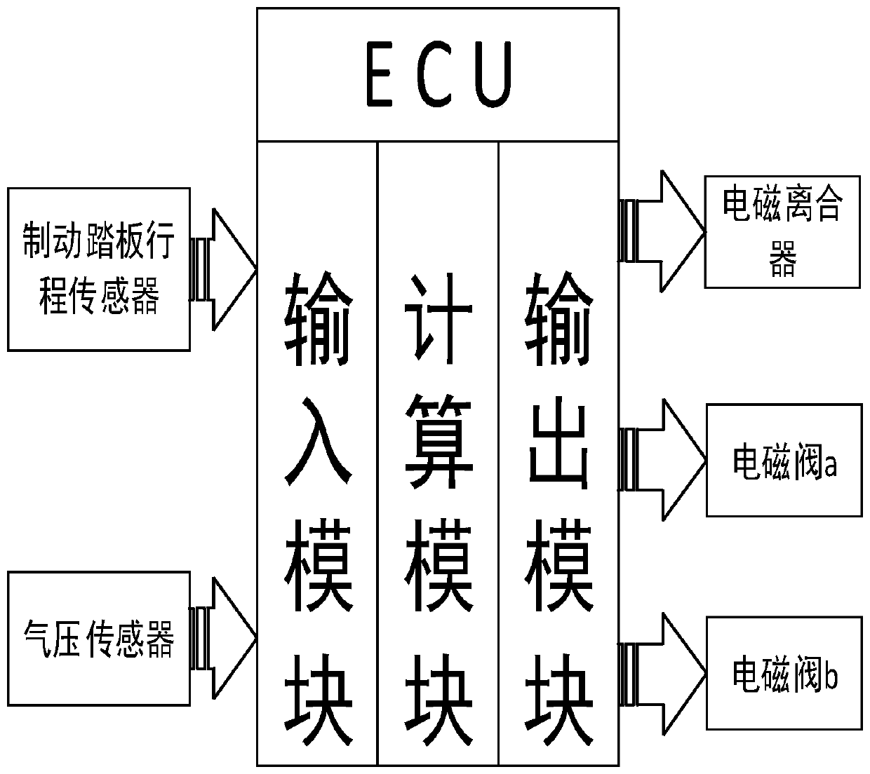
[0063] The detection mechanism detects the brake pedal stroke s and the gas pressure p signal of the first gas storage tank 15, and transmits the signal to the ECU1;

[0064] The ECU1 judges whether to brake according to the stroke s of the brake pedal. If it detects that s=0, it is judged that the vehicle is not braked. The ECU1 controls the electromagnetic clutch 9 to be disconnected, the solenoid valve a13 and the solenoid valve b17 are closed, and the auxiliary device is not activated. start up;

[0065] If s≠0, it is judged that the driver has braked, and the type of brake is judged. When it is judged as emergency braking, ECU1 controls the energy conversion mechanism to convert mechanical energy into pneumatic internal energy, and transfer the pneumatic internal energy to the ...


PUM


Abstract

The invention provides an emergency braking auxiliary device and method for a pneumatic brake. The emergency braking auxiliary device comprises a first gas storage tank, an energy conversion mechanism, a detection mechanism and an ECU. The first air storage tank is used for being connected with a brake air chamber; one end of the energy conversion mechanism is used for being connected with a poweroutput shaft, and the other end of the energy conversion mechanism is connected with a second air storage tank to convert mechanical energy into air pressure internal energy; the detection mechanismis used for detecting the stroke s of a brake pedal and the air pressure p of the first air storage tank; and the ECU is respectively connected with the detection mechanism, the energy conversion mechanism and a control valve of the first gas storage tank. During emergency braking, the first air storage tank inflates extra high-pressure air into a braking air chamber, the braking effect is enhanced, the emergency braking auxiliary function is achieved, air inflation and energy storage are conducted on the first air storage tank through the power output shaft in a vehicle during normal braking,redundant energy is rushed into the second air storage tank, and recovery of braking energy is achieved.

Description

technical field [0001] The invention belongs to the field of vehicle braking research, and in particular relates to an emergency braking auxiliary device and method for an air pressure brake. Background technique [0002] Pneumatic braking has the advantages of large braking torque, short pedal stroke and easy operation, so it is generally suitable for medium and heavy vehicles such as trucks and trailers. At the same time, it also has corresponding disadvantages, mainly two: 1. The braking response is slower than that of the hydraulic braking system. 2 need to consume the power of engine, energy consumption is higher. As an important part of active safety, emergency braking capability must be guaranteed. Due to the slow response of the air brake system, its emergency braking effect is relatively poor. In order to strengthen the emergency braking capability of the pneumatic brake system, patent application No. 201510846239.5 uses the air storage tank of the pneumatic brak...

Claims


Application Information

Patent Timeline
IPC IPC(8): B60T13/26
Inventor 徐兴汤赵王峰解炬梁聪陶涛
Owner JIANGSU UNIV
Learn More