Multi-beam combiner

A beam combiner, multi-beam technology, applied in optics, instruments, optical components, etc., can solve problems such as complex structure and difficult realization

Pending Publication Date: 2019-05-10
NAT UNIV OF DEFENSE TECH
View PDF0 Cites 7 Cited by
  • Summary
  • Abstract
  • Description
  • Claims
  • Application Information

AI Technical Summary

Problems solved by technology

[0004] The invention provides a multi-beam combiner, which is used to overcome the defects of complex structure and difficult realization of a large number of beam combiner

Method used


Image

  • Multi-beam combiner
  • Multi-beam combiner
  • Multi-beam combiner

Examples


Embodiment

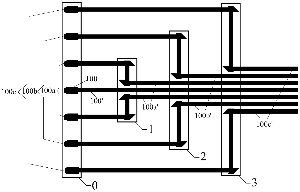
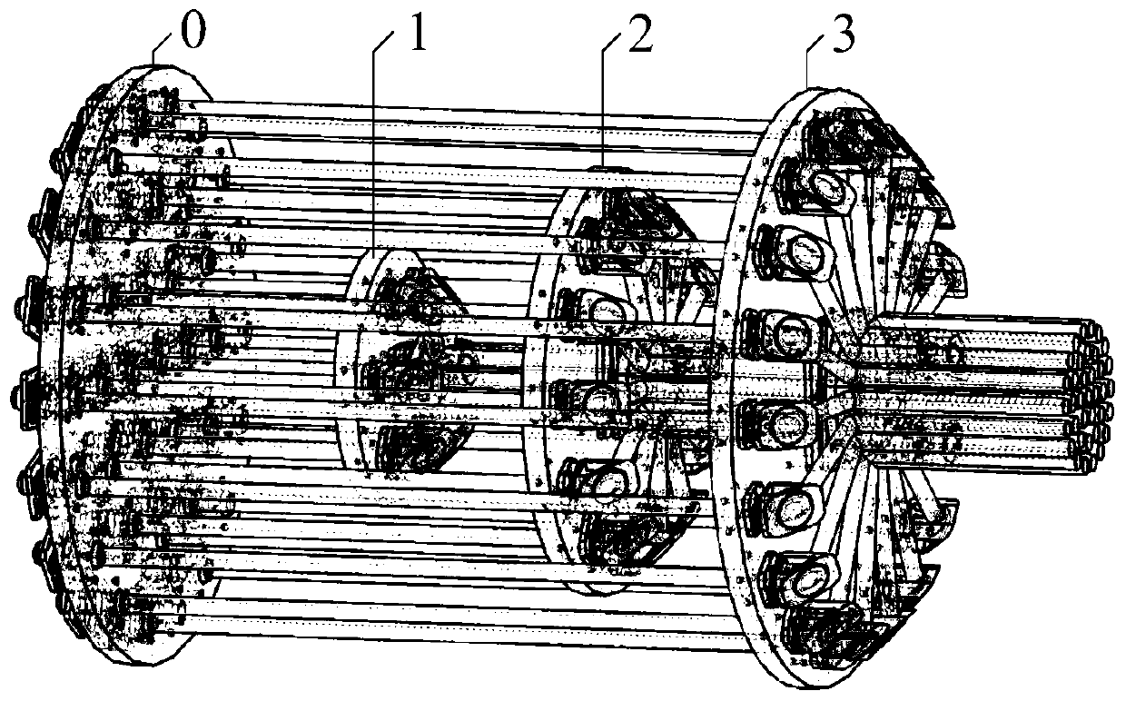
[0045] as attached figure 1 As shown, a multi-beam combiner at least includes: a beam collimator array 0 and N-stage beam combining devices, where N is an integer greater than 1. For example, it includes: a primary synthesis device 1 and a secondary synthesis device 2;

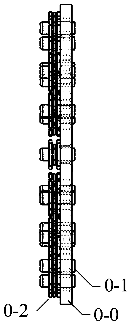
[0046] see image 3 , Figure 4, a beam collimator array 0, including several beam collimators 0-1, a collimator support plate 0-0 for providing installation support for the beam collimator 0-1, and a plurality of tilt adjustment frames 0-2 It is used to adjust the angle and position of the beam collimator 0-1, and it is arrayed layer by layer from the center to the edge, and the beam collimators of each layer are arranged in a closed shape on the collimator support plate 0-0; each layer Beam collimators are arranged on the collimator support plate 0-0 in a regular polygon or circle; in order to improve the concentration of the final beam concentration, the array shape of each layer of beam collimators is r...

Embodiment 1

[0070] see Figure 2-Figure 14 , the present embodiment discloses a reflective cascade multi-beam combiner. On the basis of the above-mentioned embodiments, the first-level combining unit, the second-level combining unit, and the third-level combining unit all include a number of 5 the same number) adjustable substrates, each of which includes:

[0071] The adjustable base 7 is installed on the side of the first support plate or the second support plate or the third support plate that is away from the collimator support plate 0-0, and is provided with output for the beam collimator the central hole through which the beam passes;

[0072] One end of the mirror mounting plate is hinged on the adjustable base 7, and the other end is mounted on the adjustable base 7 through an adjustable stud to adjust the inclination angle between the mirror mounting plate and the adjustable base 7 ; The external reflective mirror 5 is installed on the side of the mirror mounting plate close to...

Embodiment 2

[0088] This embodiment provides a transmissive cascaded multi-beam combiner, see Figure 15 , each level of beam combining device n includes: the nth beam combining support plate n-0, k n Prism-shaped beam transmitting body 8-n: in this embodiment, it is a three-stage cascade, n=3.

[0089] see Figure 16-21 , the central positions of the first-level support plate 1-0, the second-level support plate 2-0, and the third-level support plate 3-0 are all provided with a central hole, and the first-level prismatic beam transmission body 8-1 surrounds the first-level The central hole of the support plate 1-0 is radially arranged, the secondary prismatic beam transmitting body 8-2 is radially arranged around the central hole of the secondary support plate 2-0, and the third prism The beam-shaped beam transmitting body 8-3 is radially arranged around the central hole of the tertiary support plate 3-0;

[0090] The two ends of the prismatic light beam transmitting body have inclined ...


PUM


Abstract

The invention discloses a multi-beam combiner. The multi-beam combiner comprises an incident beam array and at least two-level synthesis devices; the incident beam array comprises several parallel incident beams; the incident beams are arrayed layer by layer from the centre to the edge on a plane vertical to the incident beams; each layer of beams can be arranged in a closed shape on the verticalplane; the at least two-level synthesis devices polymerize beam collimators around the centre beam layer by layer; each synthesis device comprises outer reflecting mirror surfaces and inner reflectingmirror surfaces; the number of the outer reflecting mirror surfaces is the same as the number of collimator layers; the outer reflecting mirror surfaces are fixed on a support plate, and arranged around the centre hole of the support plate; furthermore, the centre hole is superposed with the centre of a centre beam collimator; the number of the inner reflecting mirror surfaces is the same as thenumber of outer reflecting surfaces; the inner reflecting mirror surfaces are fixed on the support plate; and the centre hole around the support plate is arranged in the radial direction, and positioned among the outer reflecting mirror surfaces and the centre hole. The problems of the limited number, complex structures and the like of beams participating in synthesis in the prior art are solved;large number of beam synthesis can be realized; furthermore, the multi-beam combiner is compact in structure and easy to implement; and the synthetic light power is increased.

Description

technical field [0001] The invention relates to the technical field of beam synthesis, in particular to a cascaded multi-beam combiner, which can be used in synthetic aperture imaging and other fields requiring array beam synthesis. Background technique [0002] It is an effective way to break through the limitation of single-beam laser power and improve the total laser power by combining beams of array beams. Beam combining is to achieve efficient splicing of unit beams, and its purpose is to improve the energy concentration of the combined beams. The beam combiner is a key device to realize beam combination, and its main function is to reduce the distance between beams and increase the duty cycle of array beams. [0003] The number of beams that can be synthesized by existing multi-beam combiners is relatively small, usually 7 channels (arranged in a regular hexagon) or 9 channels (arranged in a square). If you want to achieve more beams to participate in the synthesis, t...

Claims


Application Information

Patent Timeline
IPC IPC(8): G02B27/14G02B27/10
Inventor 粟荣涛常洪祥常琦周朴马阎星马鹏飞吴坚姜曼王小林司磊许晓军陈金宝
Owner NAT UNIV OF DEFENSE TECH
Why Eureka
Try Eureka