Exposure control method of photomask

A technology of exposure control and photomask, which is applied in the direction of microlithography exposure equipment, photolithography exposure device, etc., can solve the problems that cannot meet the irregular imposition exposure processing of multi-variety photomasks, and achieve simple and easy operation of graphic processing, reduce The effect of reducing the number of mold sets and improving production efficiency and yield

Active Publication Date: 2019-05-10
SHENZHEN NEWWAY PHOTOMASK MAKING
View PDF4 Cites 1 Cited by
  • Summary
  • Abstract
  • Description
  • Claims
  • Application Information

AI Technical Summary

Problems solved by technology

[0006] At present, large-size high-resolution TFT LCD and AMOLED photomask manufacturing equipment have their own mura control function. It only needs to find an optimal mura control parameter through testing according to the pitch value of the photomask pattern; When exposing the official photomask product, the corresponding parameters can be set to achieve the purpose of optimizing mura; however, the existing equipment can only be used for graphics with a single type of full-page and regular layout; even The current state-of-the-art lithography equipment can only aim at regular typesetting masks. According to the spacing value of the graphics in the unit and the spacing value between units, a set of optimal mura control parameters can be determined through testing to achieve effective exposure. Processing, for the multi-variety random mixed-arrangement photomask, there is nothing to do, and it cannot meet the actual needs of multi-variety photomask random imposition exposure processing

Method used


Image

  • Exposure control method of photomask
  • Exposure control method of photomask
  • Exposure control method of photomask

Examples


Embodiment Construction

[0022] The present invention will be described in further detail below in conjunction with the accompanying drawings and specific embodiments. It should be understood that the following exemplary embodiments and descriptions are only used to explain the present invention, not as a limitation to the present invention, and, in the case of no conflict, the embodiments in the present invention and the features in the embodiments can be combined with each other .

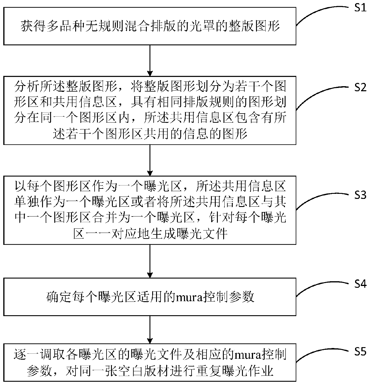
[0023] Such as image 3 As shown, the embodiment of the present invention provides a mask exposure control method, including the following steps:

[0024] Step S1, obtaining the full-page graphics of the multi-variety random mixed layout of the photomask;

[0025] Step S2, analyzing the full-page graphics, dividing the full-page graphics into several graphic areas and common information areas, graphics with the same typesetting rules are divided into the same graphic area, and the common information area contains the s...


PUM


Abstract

The embodiment of the invention relates to an exposure control method of a photomask. The exposure control method comprises the steps of acquiring a full-page pattern, which is formed by irregularly mixing and arranging various types, of the photomask; analyzing the full-page pattern, dividing the full-page pattern into a plurality of pattern regions and a sharing information region, wherein the patterns with same layout rule are divided within a pattern region, and the sharing information region comprises an information pattern shared by a plurality of pattern regions; using each pattern region as an exposure region, independently using the sharing information region as an exposure region or combining the sharing information region and one of the pattern regions as an exposure region, andgenerating an exposure file in one-to-one correspondence with regard to each exposure region; determining a mura control parameter applicable to each exposure; and calling the exposure file and the corresponding mura control parameter of each exposure region one by one, and performing repeated exposure operation on the same blank plate. With the exposure control method disclosed by the embodimentof the invention, a mura phenomenon can be effectively controlled, the production efficiency and the yield of the photomask are improved, the pattern processing is simple, the die opening sets of thephotomask are reduced, and the cost is reduced.

Description

technical field [0001] Embodiments of the present invention relate to the technical field of photomask manufacturing, and in particular, to a method for controlling exposure of a photomask. Background technique [0002] The reason for mura (mura refers to the uneven brightness of the display, causing various traces) on the mask is mainly due to regular uneven lines (uniform difference) or scanning position offset (sweeplength erro) on the mask. Produced by the photolithography machine during the exposure process. [0003] At present, most large-size masks are produced by progressive scanning laser lithography machines, and the main manufacturers are Mycronic mydata in Sweden and Heidelberg in Germany. The mainstream models are LRS series, FPS series and VPG series, and the mura produced by them are regular stripes, and the stripes are all parallel to the exposure direction. [0004] The following takes the FPS series models of Mycronic mydata as an example to analyze the c...

Claims


Application Information

Patent Timeline
Patent Type & Authority Applications(China)
IPC IPC(8): G03F7/20
Inventor 杜武兵林伟司继伟
Owner SHENZHEN NEWWAY PHOTOMASK MAKING
Why Eureka
Try Eureka