Variable-speed playback apparatus and method for digital video signals

A technology of digital information, generating device, applied in the field of devices for reproducing digital signals from a magnetic tape at a tape advance rate

Inactive Publication Date: 2002-12-25
SONY CORP
View PDF0 Cites 0 Cited by
  • Summary
  • Abstract
  • Description
  • Claims
  • Application Information

AI Technical Summary

Problems solved by technology

However, if the travel rate of that tape is shifted slightly for example to 9.48x, then it may be updated even if it is not possible at 9.5x rate

Method used


Image

  • Variable-speed playback apparatus and method for digital video signals
  • Variable-speed playback apparatus and method for digital video signals
  • Variable-speed playback apparatus and method for digital video signals

Examples


Embodiment Construction

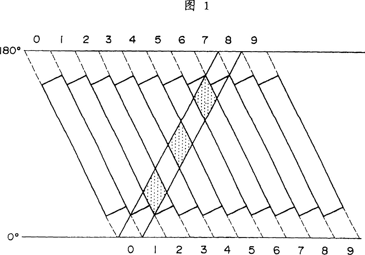
[0031] A typical head trajectory pattern obtained during a playback operation using two facing heads at a velocity 9.0 times the normal traveling tape velocity is shown in FIG. It should be noted that numerals 0 to 9 in the figure are track numbers in units of one frame. Also, since the azimuth angle of the playback head is relative to the track with an even number, the data in the shaded area is played out.

[0032] In this figure, the track starts at one end of the tape extending towards the track with track number 0 (at a drum wrap angle of 0 degrees) and ends at one end of the tape with track number 8 (at a drum wrap angle of 180 degrees) The track extends to the other end of the tape. If the tape travels exactly at 9.0 times speed, the track phase will increase at a position having a drum winding angle of 180° when the track number is counted.

[0033] In the present invention, the output of a counter is used as a reference signal, which counter resets itself periodical...


PUM


Abstract

SUMMARY OF THE INVENTION The present invention provides a variable speed playback apparatus for digital video signals in which the tape travel speed can be controlled with high precision. A track phase processing unit (33) is used in the microcomputer (25) to calculate the head track phase from the track number to be reproduced and the number of synchronous data segments. This track phase is compared with the reference track phase Ref output by a period counter (29) to generate a phase error which is supplied to the rate control unit (26).

Description

technical field [0001] The present invention relates to an apparatus for reproducing digital signals from a magnetic tape at a different tape travel rate than that at which the digital signals were recorded on the magnetic tape. Background technique [0002] A video recorder (hereinafter referred to as a digital VTR) for converting an analog video signal into digital video data, compressing the data amount, and recording and reproducing the compressed digital video data is under development. A simplified block diagram of a video signal processing system used in such a digital VTR is shown in FIG. First, video signal processing in the digital VTR will be described with reference to the figure. [0003] An input analog video signal is converted into digital video data by an A / D converter 1 before being supplied to a digital signal processing circuit 2 . When the digital video data is supplied to the digital signal processing circuit 2, the digital si...

Claims


Application Information

Patent Timeline
Patent Type & Authority Patents(China)
IPC IPC(8): H04N5/783G11B15/18G11B15/467H04N5/92H04N5/93
CPCG11B15/1875G11B15/4676G11B5/09
Inventor 吉广俊孝南云正彦山冈正人
Owner SONY CORP
Why Eureka
Try Eureka