Vacuuming oiling method for transformer, and equipment for realizing the method
A technology for oil injection equipment and transformers, which is applied in transformer/inductor cooling, inductance/transformer/magnet manufacturing, electrical components, etc. It can solve the problems that natural esters cannot be used in transformers, affect the working performance of transformers, and affect the safety of transformers. Prevent the deterioration of insulating oil, ensure the quality, and prevent the deterioration of insulating oil
- Summary
- Abstract
- Description
- Claims
- Application Information
AI Technical Summary
Problems solved by technology
Method used
Image

Examples
Embodiment 1
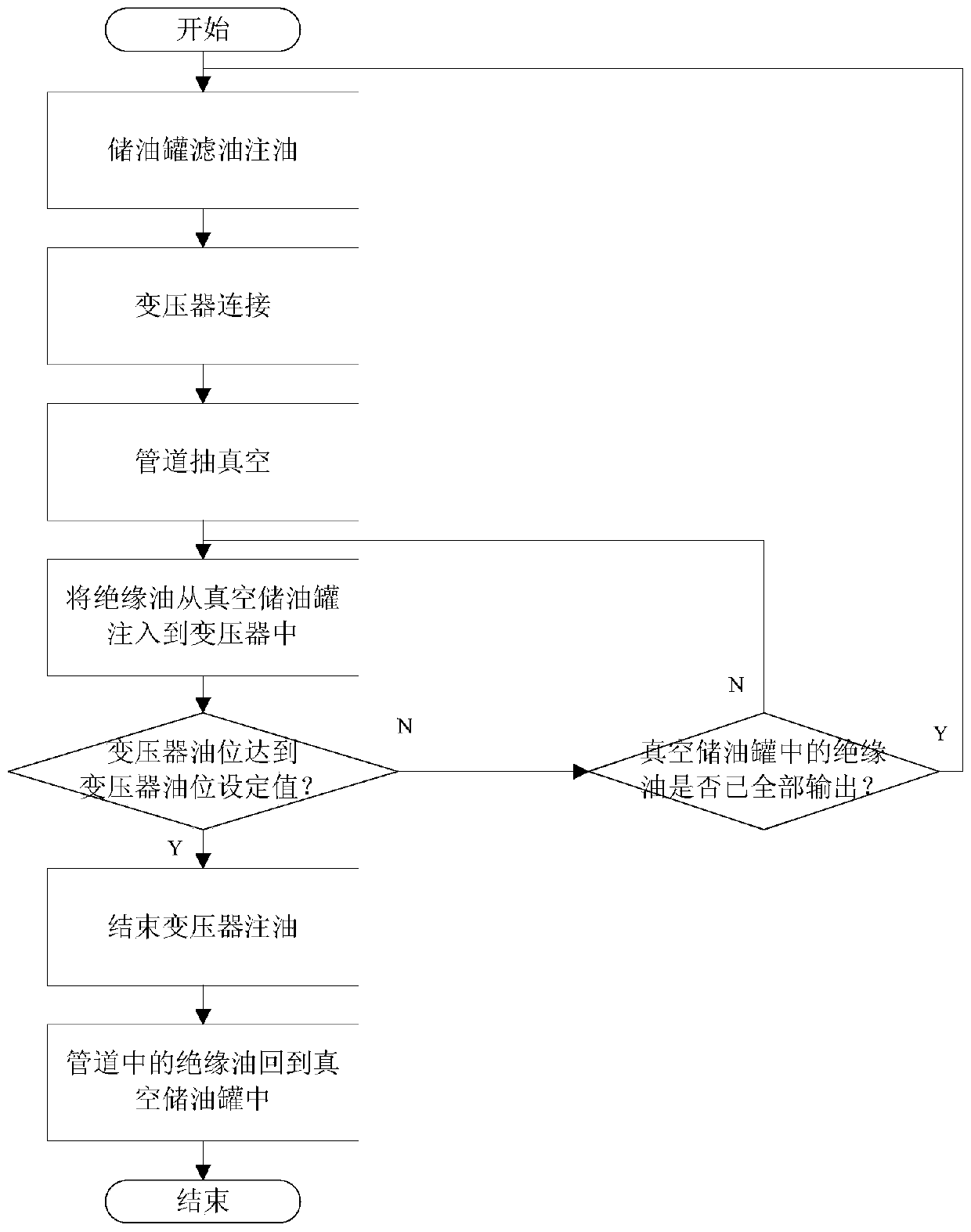
[0045] This embodiment is a transformer vacuum oiling method, which can be used for both natural ester insulating oil oiling and mineral insulating oil oiling; it includes oil storage tank filtering oil filling process, transformer connection process, transformer oiling process and return Oil process; its specific process is as follows figure 1 shown.
[0046] The oil filtering and filling process of the oil storage tank refers to vacuum filtering the insulating oil and storing it in the vacuum oil storage tank;
[0047] The step of connecting the transformer means that the vacuum oil storage tank is connected to the transformer through an adapter; the connection between the transformer and the adapter and the pipeline between the adapter and the vacuum oil storage tank are vacuumed;
[0048] The transformer oil injection process refers to injecting insulating oil from the vacuum oil storage tank into the transformer;
[0049] The oil return process refers to returning the i...
Embodiment 2
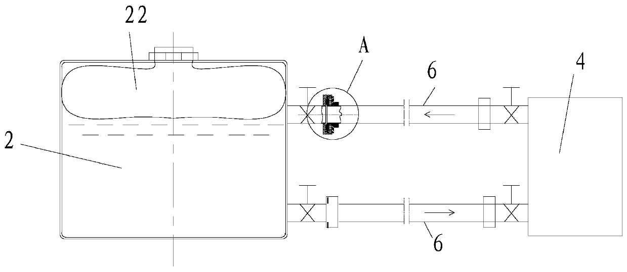
[0063] The difference between the transformer vacuum oiling equipment in this embodiment and the first embodiment is that in this embodiment, double seals are used between the pipeline two 6 and the vacuum oil storage tank 2 and between the pipeline two 6 and the vacuum oil filter 4 Connectors realize the connection, such as image 3 with Figure 4 shown. The double-seal connection has good sealing performance, preventing air from infiltrating into the oil-filled environment from the connection. The double-seal connector includes a base 23, a plate body 25, a sealing layer 26, a sealing flange 27 and a nut 28; the base 23 is provided with a concave position; the plate body 25 is arranged in the concave position, There is a sealing ring 24 between them; the sealing layer 26 is arranged on the side of the plate body 25 away from the base 23, and the sealing layer 26 is located in the concave position against the side wall of the concave position; the sealing flange 27 and the ...
Embodiment 3
[0066] The difference between the transformer vacuum oiling method in this embodiment and the first embodiment is that in this embodiment, in the process of filtering and oiling the oil storage tank, vacuum filtering the insulating oil and storing it in the vacuum oil storage tank refers to: The original insulating oil in the transformer is extracted, and the oil is vacuum filtered through a vacuum oil filter, and then stored in a vacuum oil storage tank.
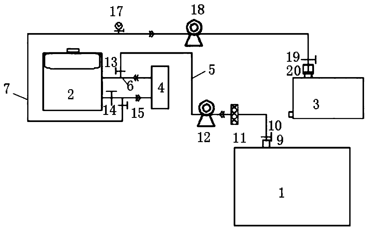
[0067] In order to realize the above transformer vacuum oiling method, this embodiment provides a transformer vacuum oiling equipment, the structure of which is as follows Figure 5 Shown; connector one 9 is connected with transformer 3, and the rest of the structure of this embodiment is the same as that of embodiment one. The original insulating oil can be discharged from the transformer as the source of insulating oil, and the original insulating oil of the transformer can be discharged, filtered, and reinjected to reali...
PUM
 Abstract
Description
Claims
Application Information
 - R&D
- Intellectual Property
- Life Sciences
- Materials
- Tech Scout
- Unparalleled Data Quality
- Higher Quality Content
- 60% Fewer Hallucinations
Browse by: Latest US Patents, China's latest patents, Technical Efficacy Thesaurus, Application Domain, Technology Topic, Popular Technical Reports.
© 2025 PatSnap. All rights reserved.Legal|Privacy policy|Modern Slavery Act Transparency Statement|Sitemap|About US| Contact US: help@patsnap.com