
Longitudinal uniform flow field flow battery and working method thereof

A flow battery, uniform flow technology, applied in fuel cell additives, regenerative fuel cells, electrolyte flow treatment, etc., can solve the problems of reducing the working efficiency of flow batteries, uneven distribution of electrolyte concentration, huge pump power consumption, etc. Achieve the effect of improving battery efficiency, reducing pump work, and improving the degree of reaction

Active Publication Date: 2019-05-10
XI AN JIAOTONG UNIV
View PDF12 Cites 0 Cited by
  • Summary
  • Abstract
  • Description
  • Claims
  • Application Information

AI Technical Summary

Problems solved by technology

[0003] Current flow batteries can be divided into two types according to the structure of the flow field: "flow-through type" and "flow-through type". Among them, the "flow-through" flow battery operates through the redox reaction of the electrolyte flowing from the side of the electrode to the other side. , this process requires the electrolyte to flow across the entire electrode surface, which brings huge pump power consumption. At the same time, due to the consumption of electrolyte during the flow process, the electrolyte concentration distribution on the electrode surface is uneven, which greatly reduces the flow battery. work efficiency
[0004] Therefore, in order to solve the problems of high electrolyte pumping work and uneven distribution of electrolyte concentration in the electrodes during the flow process of the flow battery, a high-efficiency flow battery with uniform reaction and low pumping work is urgently needed.

Method used


Image

  • Longitudinal uniform flow field flow battery and working method thereof
  • Longitudinal uniform flow field flow battery and working method thereof
  • Longitudinal uniform flow field flow battery and working method thereof

Examples


Embodiment Construction

[0037]The present invention will be described in further detail below in conjunction with the accompanying drawings and specific embodiments, but not as a limitation of the present invention.

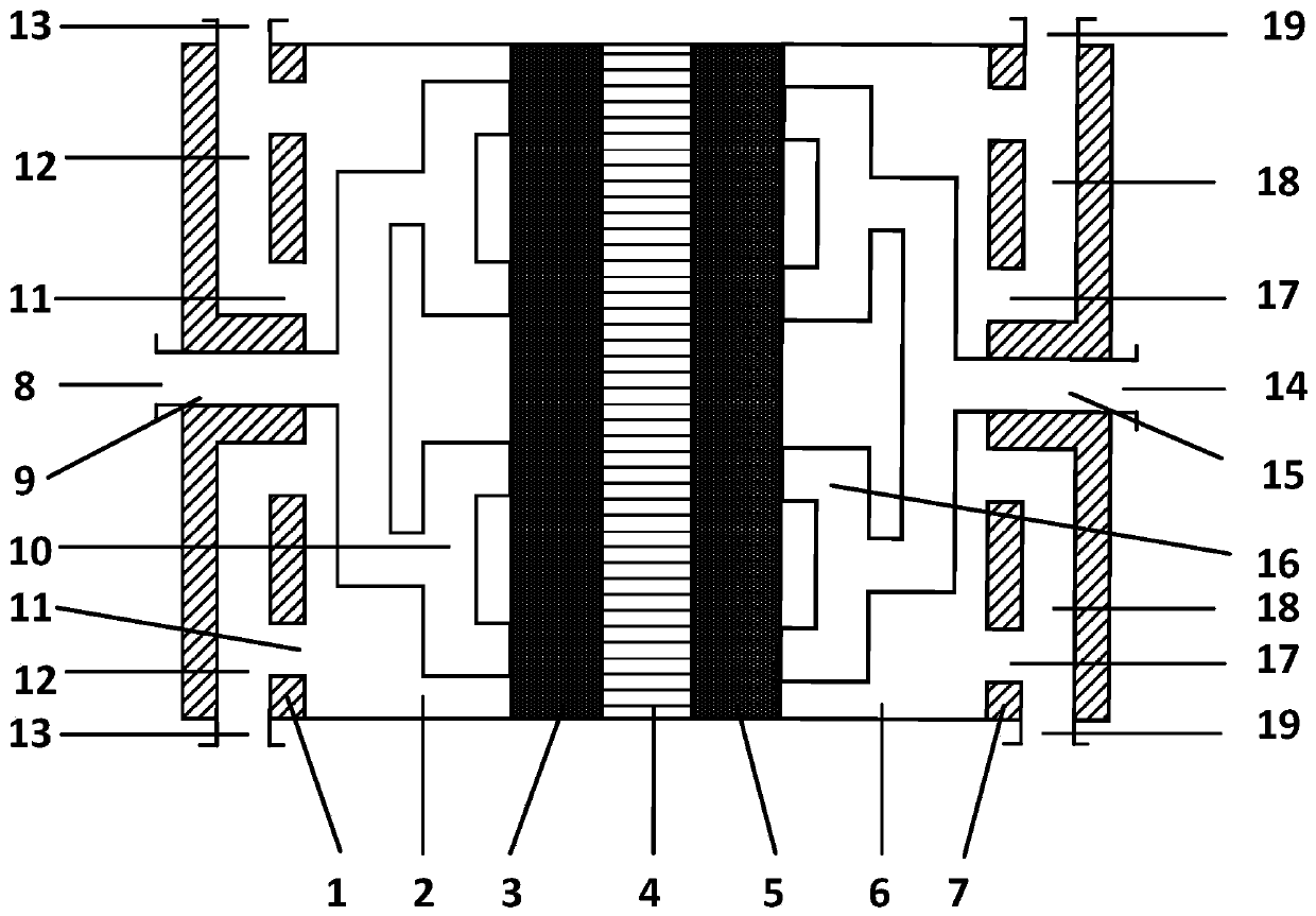
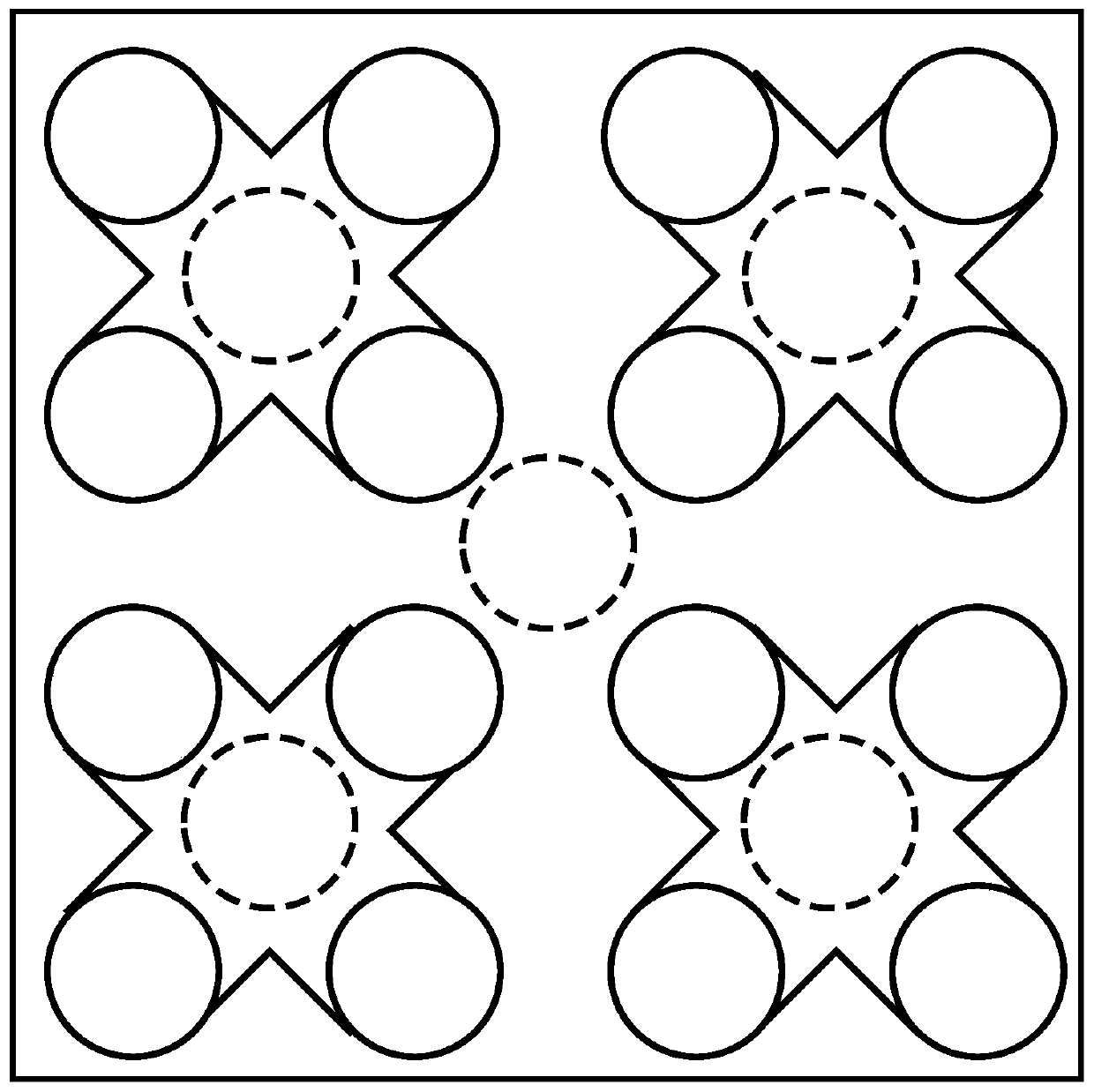
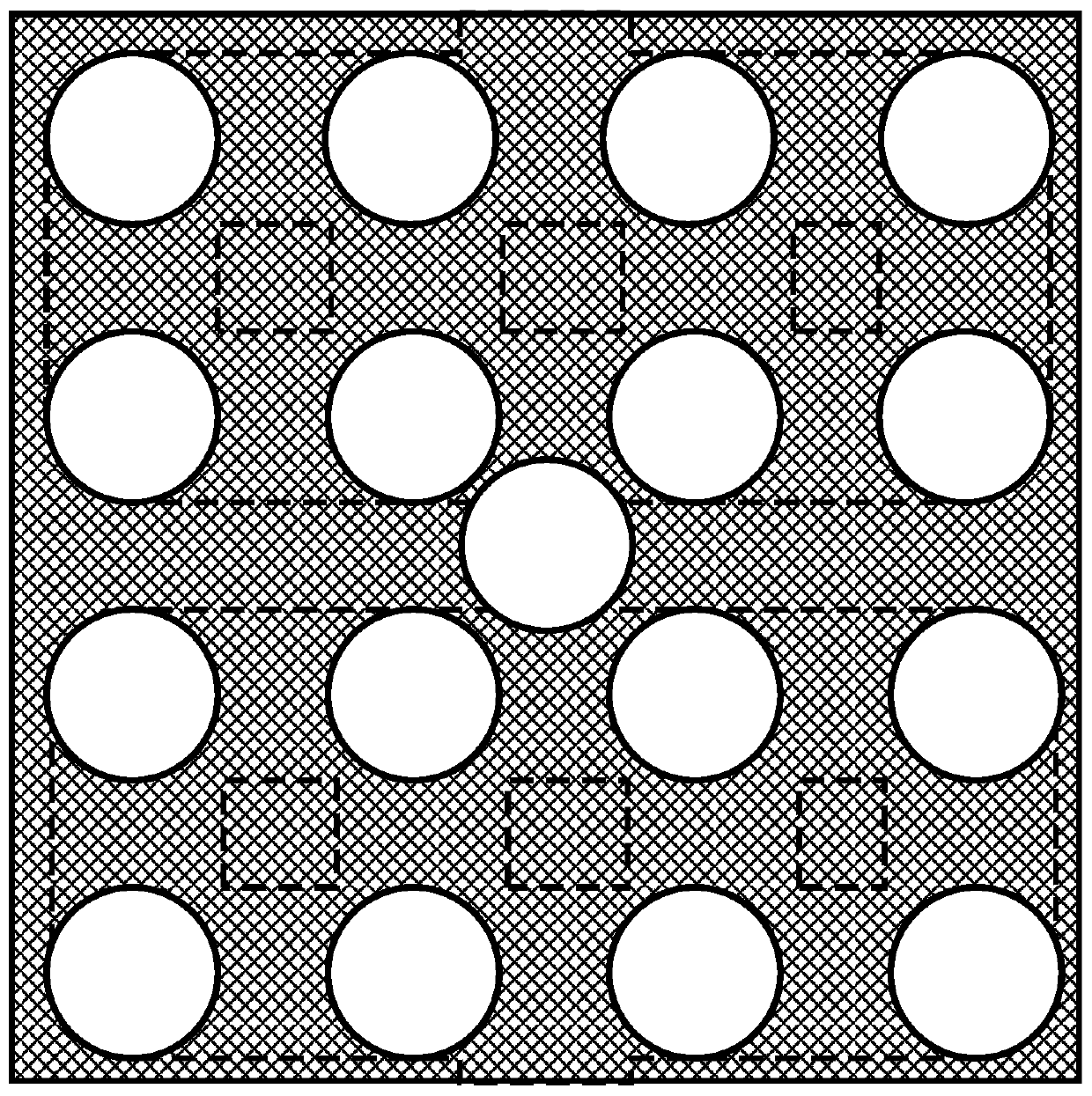
[0038] see Figure 1-3 , the longitudinal uniform flow field flow battery of the present invention includes a positive electrolyte return area 1, a positive electrolyte supply area 2, a positive electrode 3, an exchange membrane 4, a negative electrode 5, and a negative electrolyte arranged on the liquid flow battery body. The supply area 6 and the negative electrode electrolyte return area 7; the positive electrode electrolyte supply area 2 is connected with the positive electrode electrolyte return area 1 and the positive electrode 3, the positive electrode 3 and the negative electrode 5 are separated by the exchange membrane 4, and the negative electrode electrolyte supply area 6 It is connected with the negative pole electrode 5 and the negative pole electrolyte reflow area 7 .

[...


PUM


Abstract

The invention discloses a longitudinal uniform flow field flow battery and a working method thereof. The flow battery comprises a positive electrode electrolyte recirculation zone, a positive electrode electrolyte supply zone, a positive electrode, an exchange membrane, a negative electrode, a negative electrode electrolyte supply zone and a negative electrode electrolyte recirculation zone, whichare arranged on a flow battery body; and the electrolyte supply zone is a cavity having a flow path and a hollow cavity excluding the flow path, the electrolyte supply zone is provided with an electrolyte distribution flow path and a dendritic electrolyte supply branch, a novel stepwise dendritic longitudinal inflow flow field is adopted to ensure that the electrolyte can be directly and uniformly supplied to the surface of the electrode, thereby improving the reaction degree of the electrolyte and improving the efficiency of the battery.

Description

technical field [0001] The invention relates to the technical field of liquid flow batteries, in particular to a liquid flow battery with a longitudinal uniform flow field and a working method thereof. Background technique [0002] With the increasingly serious problems of environmental pollution and shortage of fossil energy, people are developing and utilizing renewable energy such as wind energy and solar energy more and more widely. Grid integration presents enormous challenges. Large-scale energy storage technology is an important means to solve the intermittent problem of renewable energy generation, and it is also a key technology to solve the contradiction between supply and demand in the power system, ensure the stable operation of the power grid, and develop a smart grid. Existing energy storage technologies are difficult to be widely used due to special geological and geographical requirements, low energy density, high cost, and low cycle life. For example, the ...

Claims


Application Information

Patent Timeline
IPC IPC(8): H01M8/18H01M8/04276
CPCY02E60/50
Inventor 李印实王睿
Owner XI AN JIAOTONG UNIV
Learn More