Textile cleaning device

A cleaning device and textile technology, applied in textiles and papermaking, equipment configuration for processing textile materials, mechanical cleaning, etc., can solve problems such as poor cleaning effect, hair balls, and fabric wrinkles, so as to improve cleaning effect and work efficiency Effect

Inactive Publication Date: 2019-05-14
JIAXING VOCATIONAL TECHN COLLEGE
View PDF12 Cites 13 Cited by
  • Summary
  • Abstract
  • Description
  • Claims
  • Application Information

AI Technical Summary

Problems solved by technology

This solution solves the problem of poor cleaning effect on textiles such as thread ends and hair balls in the prior art
[0004] However, the textile cleaning device provided in the above technical solution still has many disadva

Method used


Image

  • Textile cleaning device
  • Textile cleaning device
  • Textile cleaning device

Examples


Embodiment 1

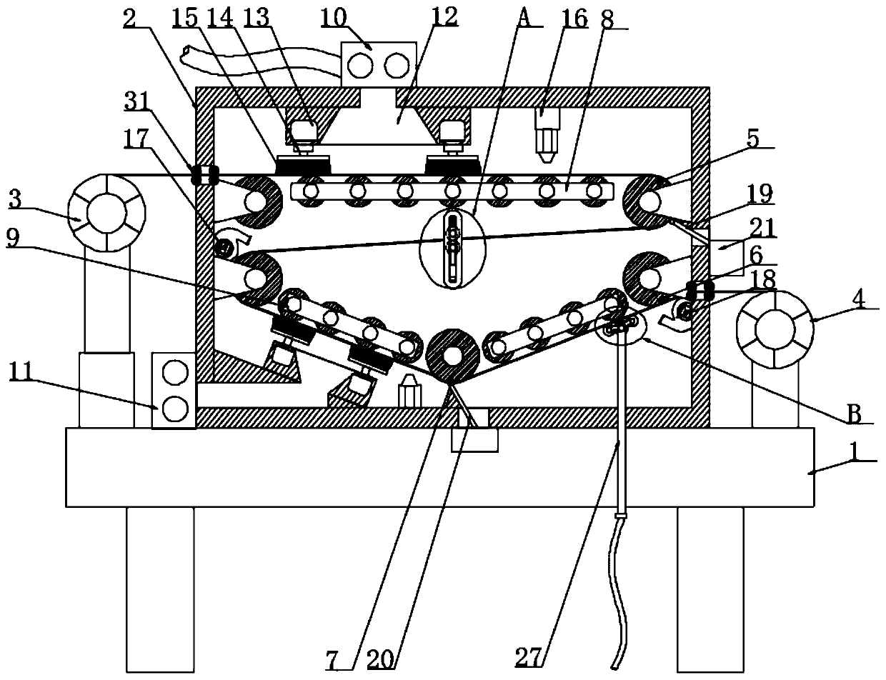
[0025] according to Figure 1-4 A textile cleaning device shown includes a frame 1, a box body 2 is arranged on the top of the frame 1, and an unwinding roller 3 is arranged on one side of the box body 2, and the box body 2 is far away from the unwinding roller 3 One side of the box body 2 is provided with a winding roller 4, and the inside of the box body 2 is provided with two symmetrically distributed first turning rollers 5, and the bottom of the first turning roller 5 is provided with two symmetrically distributed second turning rollers 6, A third turning roller 7 is arranged between the two second turning rollers 6, and a first bracket 8 is fixedly connected between the two first turning rollers 5, and the third turning roller 7 is connected to the two first turning rollers 5. The second support bracket 9 is arranged between the two steering rollers 6, the first dust suction pump 10 is provided on the top of the box body 2, the second dust suction pump 11 is arranged on ...

Embodiment 2

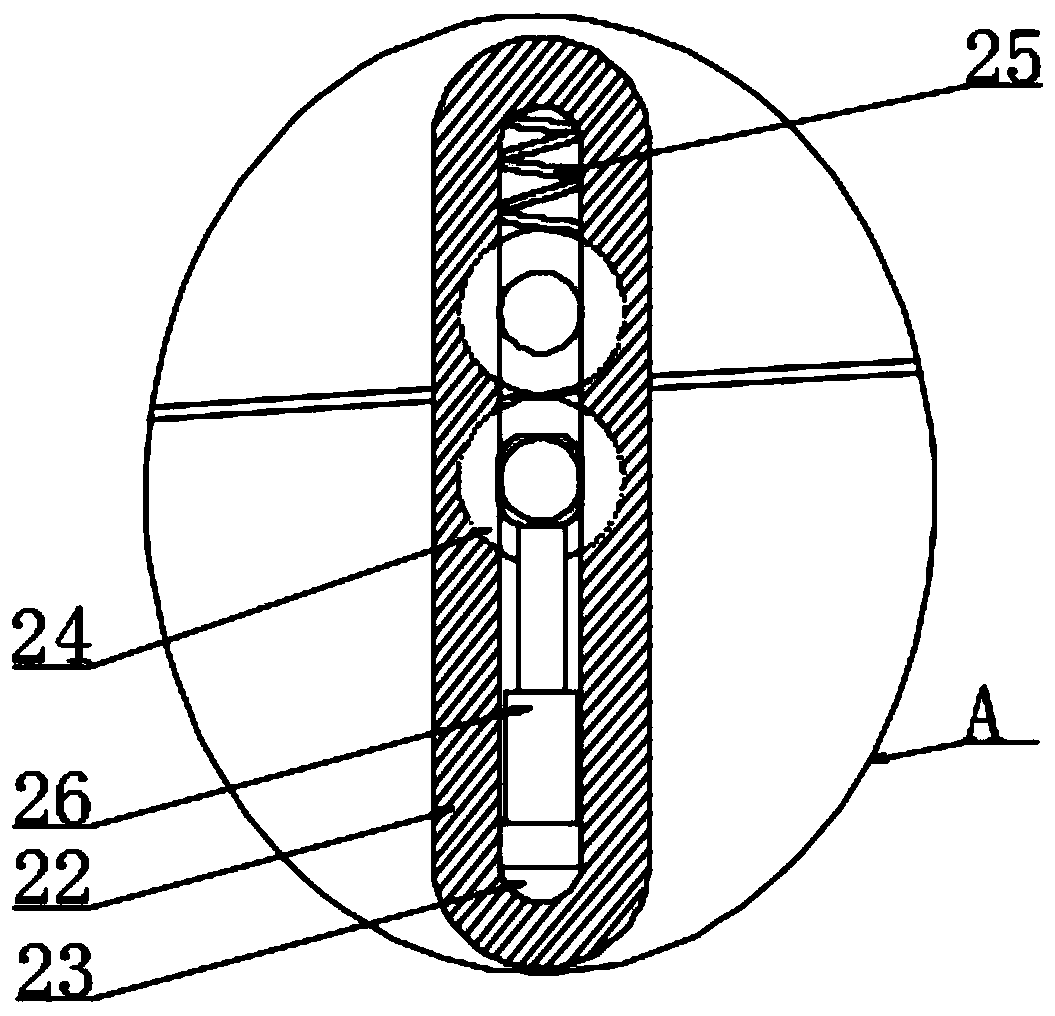
[0028] according to figure 1 and 3 As shown in a textile cleaning device, a tension adjustment device is provided between the two first turning rollers 5 and the two second turning rollers 6, and the tension adjustment device includes two symmetrically distributed fixing plates 22 A chute 23 runs through one side of the fixed plate 22, and two parallel adjusting rollers 24 are slidably connected in the chute 23, a compression spring 25 is provided at the top of the chute 23, and a compression spring 25 is provided at the bottom of the chute 23. There is a second cylinder 26, through the tension adjustment device, the output end of the second cylinder 26 pushes the slider to make the adjustment roller 24 slide in the chute 23, under the action of the compression spring 25, the two adjustment rollers 24 clamp the woven fabric, It can easily adjust the tightness of the textile and improve the cleaning effect of the textile;

[0029] according to image 3As shown in a textile c...


PUM


Abstract

The invention discloses a textile cleaning device, and particularly relates to the technical field of textiles. The textile cleaning device comprises a rack, a box body is arranged at the top of the rack, an unwinding roller is arranged on one side of the box body, and a winding roller is arranged on the side, away from the unwinding roller, of the box body; and two symmetrically-distributed firststeering rollers are arranged in the box body, and two symmetrically-distributed second steering rollers are arranged at the bottoms of the first steering rollers. According to the textile cleaning device, output shafts of motors are in transmission connection with sweeping wheels, thus dust and fiber impurities on the surface of a textile cloth are swept and pumped out by dust suction pumps fromdust suction openings, atomizing spraying heads spray water vapor to moisten the textile cloth, dust fall in the box body is achieved, meanwhile, scraper plates conveniently scrap hair balls on the surface of the textile cloth, the first dust suction pump and the second dust suction pump are arranged on the two sides of the textile cloth correspondingly, the first scraper plate and the second scraper plate are arranged on the two sides of the textile cloth correspondingly, thus double-sided clearing is achieved, the working efficiency is improved, a first air heater and a second air heater are arranged on the two sides of the textile cloth correspondingly, thus the textile cloth can be effectively dried, and the textile cloth is leveled by matching with the atomizing spraying heads.

Description

technical field [0001] The invention relates to the technical field of textiles, and more specifically, the invention relates to a textile cleaning device. Background technique [0002] Textiles are processed and woven from textile fibers. During the weaving process, textiles may have tiny fluff and foreign matter adhesion. When textiles rub against each other, hair balls are easily produced, which affects the appearance quality and gives a The business suffered great losses. [0003] The Chinese patent application publication number CN 107916554 A discloses a textile cleaning device, including a frame, a conveying part, a driving part and a cleaning part, and the conveying part includes a discharge roller, a take-up roller and a roller between the two. Conveying rollers; the driving part includes a motor fixed on the frame, a cam and a moving rod against the cam, and the moving rod is fixed to the main blade; the cleaning part includes a vacuum cleaner, a dust suction pipe...

Claims


Application Information

Patent Timeline
IPC IPC(8): D06G1/00D06B1/02D06B15/09D06B23/20D06C13/00
Inventor 周芬
Owner JIAXING VOCATIONAL TECHN COLLEGE
Why Eureka
Try Eureka