
Mounting device of side slope deformation monitoring device

A technology of monitoring device and installation device, which is applied in the direction of antenna support/installation device, electromagnetic measurement device, circuit device, etc., to achieve the effects of neat appearance, improved installation efficiency, and guaranteed equipment safety

Pending Publication Date: 2019-05-14
HUNAN LIANZHI MONITORING TECH CO LTD
View PDF2 Cites 0 Cited by
  • Summary
  • Abstract
  • Description
  • Claims
  • Application Information

AI Technical Summary

Problems solved by technology

[0006] The purpose of the present invention is to provide an installation device for a slope deformation monitoring device. The installation device adopts a modular design, which can not only realize the early installation and debugging of the monitoring elements in the slope deformation monitoring device, but also facilitate transportation and effectively solve the difficulty of on-site installation and construction. At the same time, the installation device fully considers the ventilation and heat dissipation circulation of the internal monitoring components, as well as the convenience of regular inspection and maintenance by personnel in the later period, and is very practical.

Method used


Image

  • Mounting device of side slope deformation monitoring device
  • Mounting device of side slope deformation monitoring device
  • Mounting device of side slope deformation monitoring device

Examples


Embodiment Construction

[0030] The embodiments of the present invention will be described in detail below with reference to the accompanying drawings, but the present invention can be implemented in various ways defined and covered by the claims.

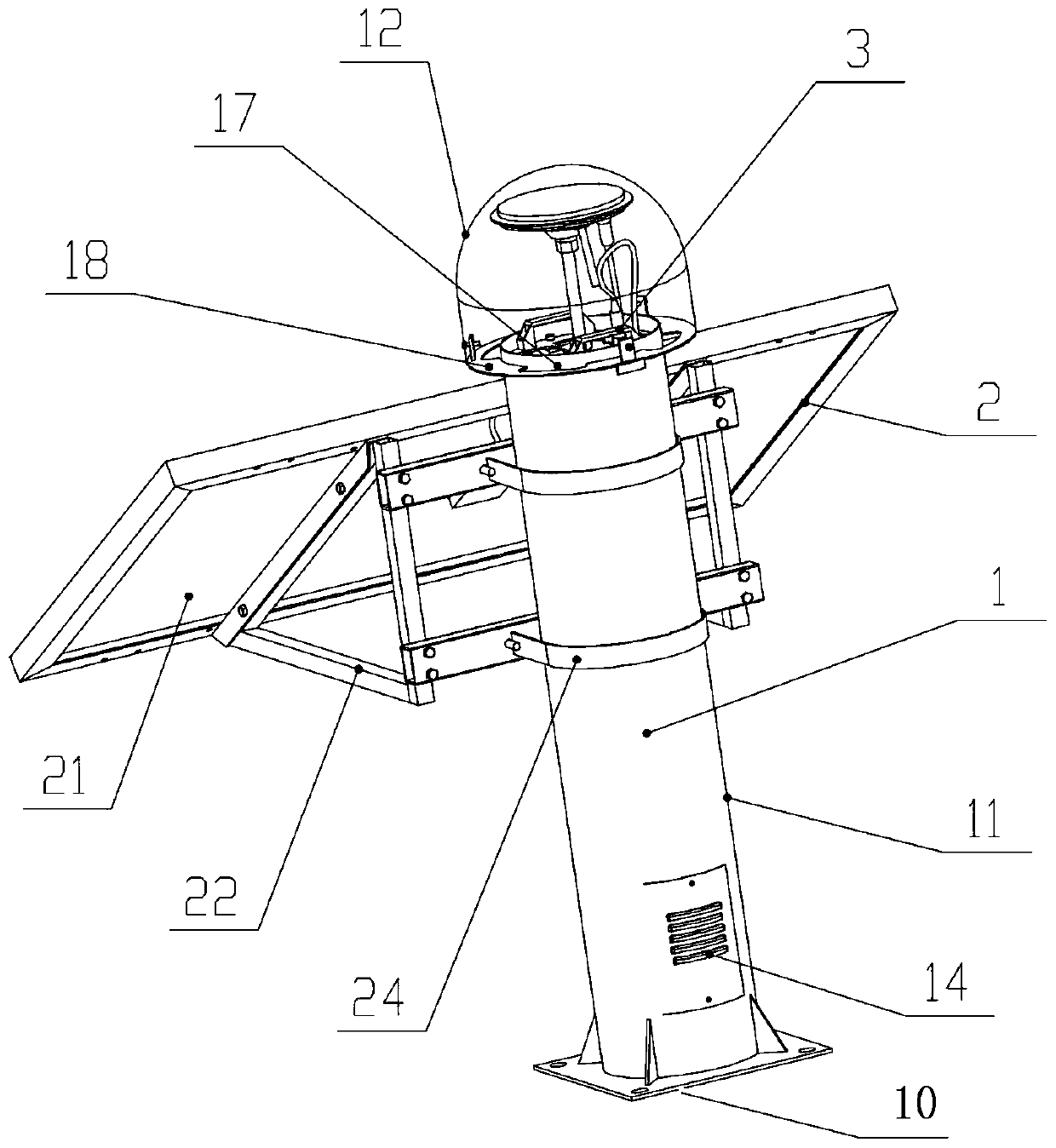
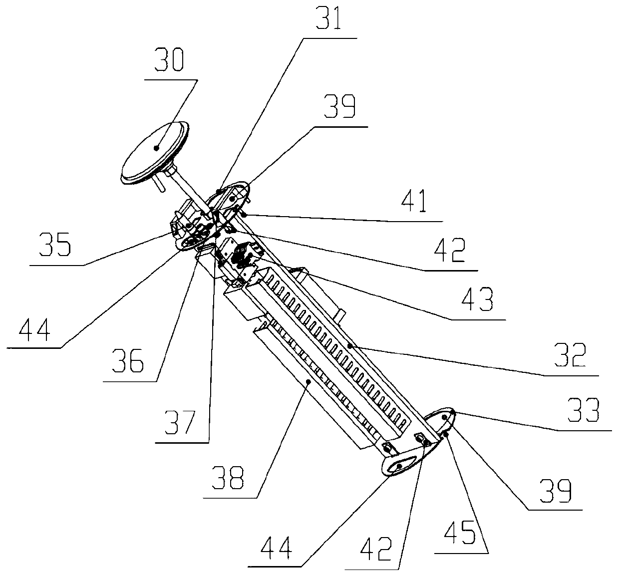
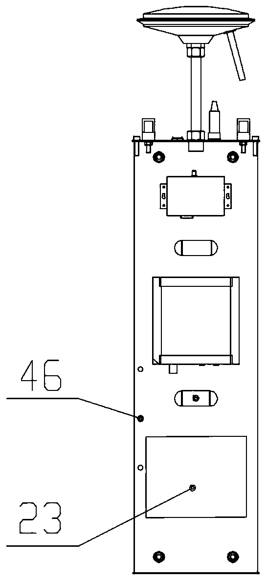
[0031] see Figure 1 to Figure 5, the present invention provides an installation device for a slope deformation monitoring device, including a housing part 1, a detachable core assembly 3 and a photovoltaic power generation assembly 2; the housing part 1 includes an installation base 10, a cylinder 11 and a radome 12; The detachable core assembly 3 includes a pull-up plate 31, a pull-down plate 33 and a mounting plate 32; the photovoltaic module 2 includes a photovoltaic panel 21, a photovoltaic panel support 22 and a lithium battery 23;

[0032] The cylinder 11 is arranged on the installation base 10, the outer wall of the upper end of the cylinder is welded with an annular plate 18, and the inner diameter of the annular plate is larger than the outer dia...


PUM


Abstract

The invention discloses a mounting device of a side slope deformation monitoring device. The mounting device of the side slope deformation monitoring device comprises three parts: a shell part, a detachable core component and a photovoltaic power generation component, wherein each part is independent of each other and can form an entirety by itself, and can be transported independently and installed conveniently; the mounting device of the side slope deformation monitoring device can be assembled quickly through bolts during on-site construction, therefore, the problems of difficult transportation and difficult installation are effectively solved; wherein the detachable core component is designed as a mode that an upper pulling plate and a lower pulling plate clamp a mounting plate; a wiring duct and a line bank are arranged on one side of the mounting plate, and monitoring components are centralizedly arranged on the other side of the mounting plate, so that the monitoring componentscan be arranged on the mounting plate in a standardized and unified manner, which facilitates the early installation and debugging of the monitoring components, and greatly improves the work efficiency; meanwhile, the detachable core component has normative wiring and neat appearance, which is easy for later inspection and maintenance; in addition, the outer shell cylinder is provided with a special heat-dissipating and moisture-proof design, which effectively ensures the working proper humidity and heat dissipation effect of the monitoring components.

Description

technical field [0001] The invention relates to the technical field of installation devices, in particular to an installation device for a slope deformation monitoring device. Background technique [0002] The structural safety of transportation infrastructure has attracted more and more attention in recent years. The traditional manual monitoring technology has been difficult to meet the needs in terms of effectiveness, data volume and intuitiveness. The new automatic monitoring technology is developing and advancing steadily; automatic monitoring technology The types of engineering application technologies involved are very wide, including sensor technology, communication technology, Internet technology, etc. One of the most basic and critical aspects is the perception and data acquisition of on-site status, which requires that all hardware acquisition devices must be deployed To the top of the monitored structure, and the environment of the monitored structure is generall...

Claims


Application Information

Patent Timeline
IPC IPC(8): G01B7/16H01Q1/12H01Q1/42H02J7/35H05K7/20
CPCY02E10/56
Inventor 梁晓东周俊华熊用杨振武赵莉李熙
Owner HUNAN LIANZHI MONITORING TECH CO LTD
Learn More