
Optical fiber and GNSS-based high-precision wide-range three-dimensional deformation monitoring device

A technology of three-dimensional deformation and monitoring devices, which is applied in the direction of measuring devices, optical devices, electromagnetic measuring devices, etc., can solve the problems of larger sensor size, inability to monitor, and inability to obtain three-dimensional deformation, so as to prevent fiber breakage, The effect of large measurement range

Pending Publication Date: 2019-05-14
THE UNIV OF NOTTINGHAM NINGBO CHINA
View PDF12 Cites 0 Cited by
  • Summary
  • Abstract
  • Description
  • Claims
  • Application Information

AI Technical Summary

Problems solved by technology

Excessively increasing the fiber length between the lead-in points will cause the size of the sensor to increase, which is often not conducive to the layout of the sensor
In addition, there is another disadvantage of using the grating fiber technology, that is, the grating fiber technology can only monitor the relative deformation of the fiber length between the two lead-in points. When the two lead-in points change the same distance in the same direction, the grating fiber Technology cannot detect this type of deformation
Finally, grating optical fiber technology can only obtain the deformation in the direction of fiber laying, and cannot obtain the deformation in three-dimensional directions like GNSS technology
[0006] Therefore, the GNSS monitoring technology has the problem of low precision, while the grating fiber optic monitoring technology has the problem of limited deformation range and the inability to obtain three-dimensional deformation monitoring results.

Method used


Image

  • Optical fiber and GNSS-based high-precision wide-range three-dimensional deformation monitoring device
  • Optical fiber and GNSS-based high-precision wide-range three-dimensional deformation monitoring device
  • Optical fiber and GNSS-based high-precision wide-range three-dimensional deformation monitoring device

Examples


Embodiment

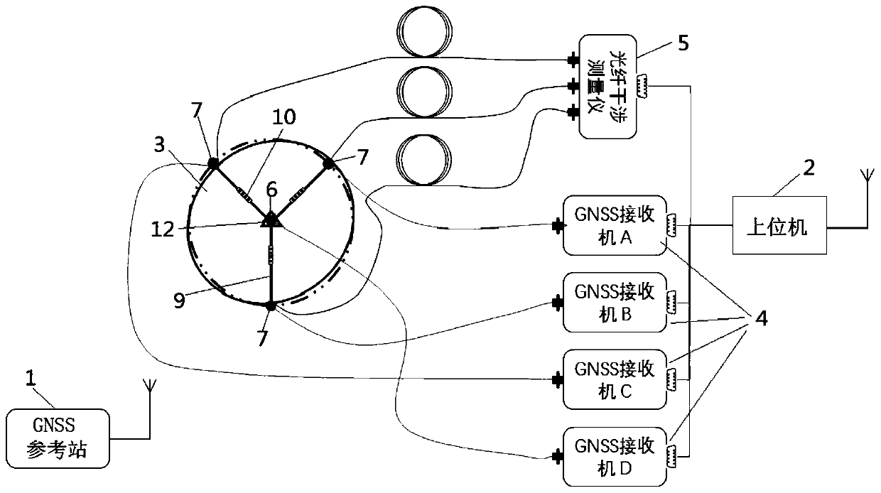
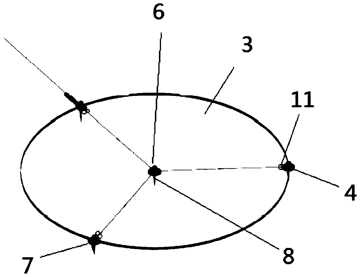
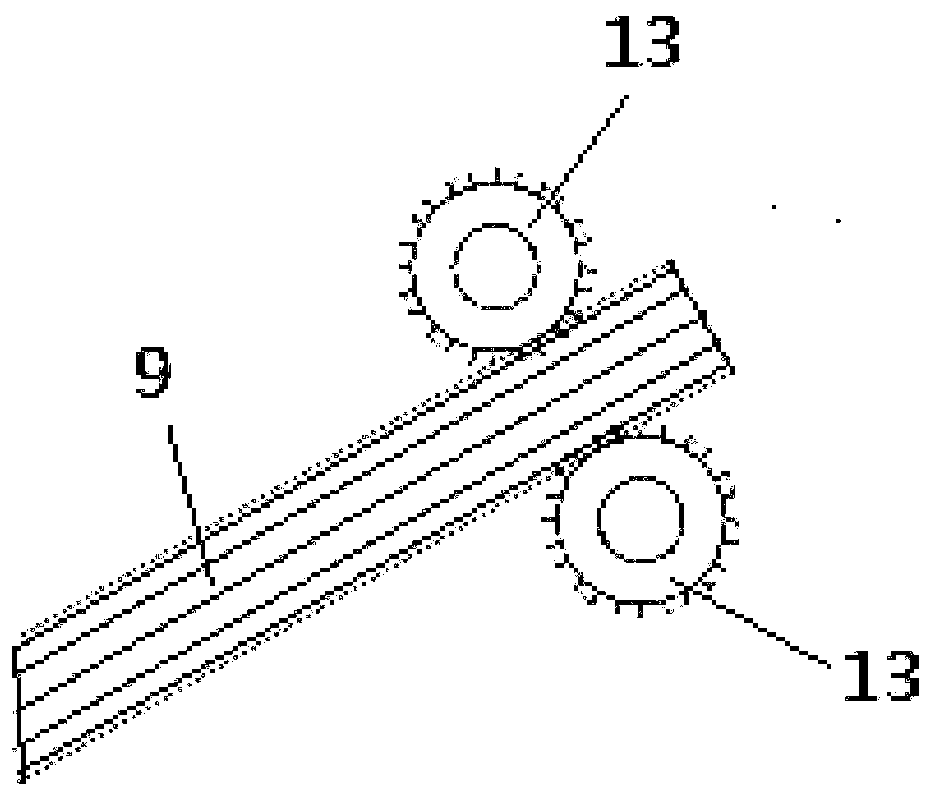
[0022] Such as figure 1 , figure 2 , image 3 As shown, a high-precision and large-range three-dimensional deformation monitoring device based on optical fiber and GNSS includes a GNSS reference station 1, a host computer 2, a substrate 3, four GNSS receivers 4, and an optical fiber interferometer 5. The substrate 3 is provided with a central lead contact 6 and three peripheral lead contacts 7 surrounding the central lead contact 6, and the central lead contact 6 and the three peripheral lead contacts 7 are all provided for contact with the measured object. A fixed fastening device 8, such as a rivet, the three peripheral lead contact points 7 and the central lead contact point 6 are connected to form a Y shape through an optical fiber 9 and a grating sensor 10, and the substrate 3 is also provided for adjustment A device 11 for automatically adjusting the length of each side of the Y-shaped optical fiber 9, the four GNSS receivers 4 are respectively arranged at the central le...


PUM


Abstract

The invention discloses an optical fiber and GNSS-based high-precision wide-range three-dimensional deformation monitoring device. The device is characterized by comprising a GNSS reference station, an upper computer, a base plate, four GNSS receivers and an optical fiber interference measuring instrument; the base plate is provided with a central lead point and three peripheral lead points aroundthe central lead point; the three peripheral lead points and the central lead point are connected in a Y shape through an optical fiber and a grating sensor; an automatic length adjusting device usedfor adjusting the length of each side of the Y-shaped optical fiber is further arranged on the base plate; the four GNSS receivers are arranged at the center lead point and the three peripheral leadpoints respectively; the three peripheral lead points are connected with three interfaces of the optical fiber interference measuring instrument; and a reflecting device is arranged at the center leadpoint. The optical fiber and GNSS-based high-precision wide-range three-dimensional deformation monitoring device can perform three-dimensional measurement, and is high in measuring precision and wide in range.

Description

Technical field [0001] The invention relates to the technical field of deformation monitoring, in particular to a high-precision large-range three-dimensional deformation monitoring device based on optical fiber and GNSS. Background technique [0002] The current deformation monitoring methods for slowly deforming objects mainly include Global Navigation Satellite System (GNSS) including GPS Beidou satellite navigation and positioning system, and grating fiber technology. The accuracy that can be achieved by the deformation monitoring of the monitored object is the main performance index for evaluating the monitoring device. [0003] However, GNSS monitoring technology and grating fiber technology have the following defects when monitoring deformation: [0004] GNSS technology: L-band GNSS technology can be used for automatic deformation monitoring of the monitored object all day and all-weather. The deformation monitoring accuracy can theoretically reach 2mm, but in actual applica...

Claims


Application Information

Patent Timeline
Patent Type & Authority Applications(China)
IPC IPC(8): G01B11/16G01B7/16G01S19/42G01S19/53
Inventor 唐旭克雷格·汉考克格辛·温·罗伯茨赵海波沃纳·林哈特李宸栋程存毅
Owner THE UNIV OF NOTTINGHAM NINGBO CHINA
Learn More