
Stator tooth module, stator, motor and winding method of winding in stator tooth module

A stator tooth and winding technology, applied in the field of stator tooth module, stator, motor, and winding winding, can solve the problems of high winding manufacturing cost, reduced slot full rate, and high requirements for winding machines, and achieves convenient winding and low requirements. , the effect of reducing manufacturing costs

Pending Publication Date: 2019-05-14
NINGBO SHENGLONG AUTOMOTIVE POWERTRAIN SYSTEM CO LTD
View PDF0 Cites 5 Cited by
  • Summary
  • Abstract
  • Description
  • Claims
  • Application Information

AI Technical Summary

Problems solved by technology

It can be seen from the above that the multi-strand parallel winding method not only has high requirements on the winding machine, but also makes the winding manufacturing cost high, and it is difficult for the winding machine to accurately control the arrangement of the internal coils of the winding when winding the winding, so that the winding is completed. The coils within the winding are often disorderly, which reduces the slot fill rate and limits the performance of the motor

Method used


Image

  • Stator tooth module, stator, motor and winding method of winding in stator tooth module
  • Stator tooth module, stator, motor and winding method of winding in stator tooth module
  • Stator tooth module, stator, motor and winding method of winding in stator tooth module

Examples


Embodiment 1

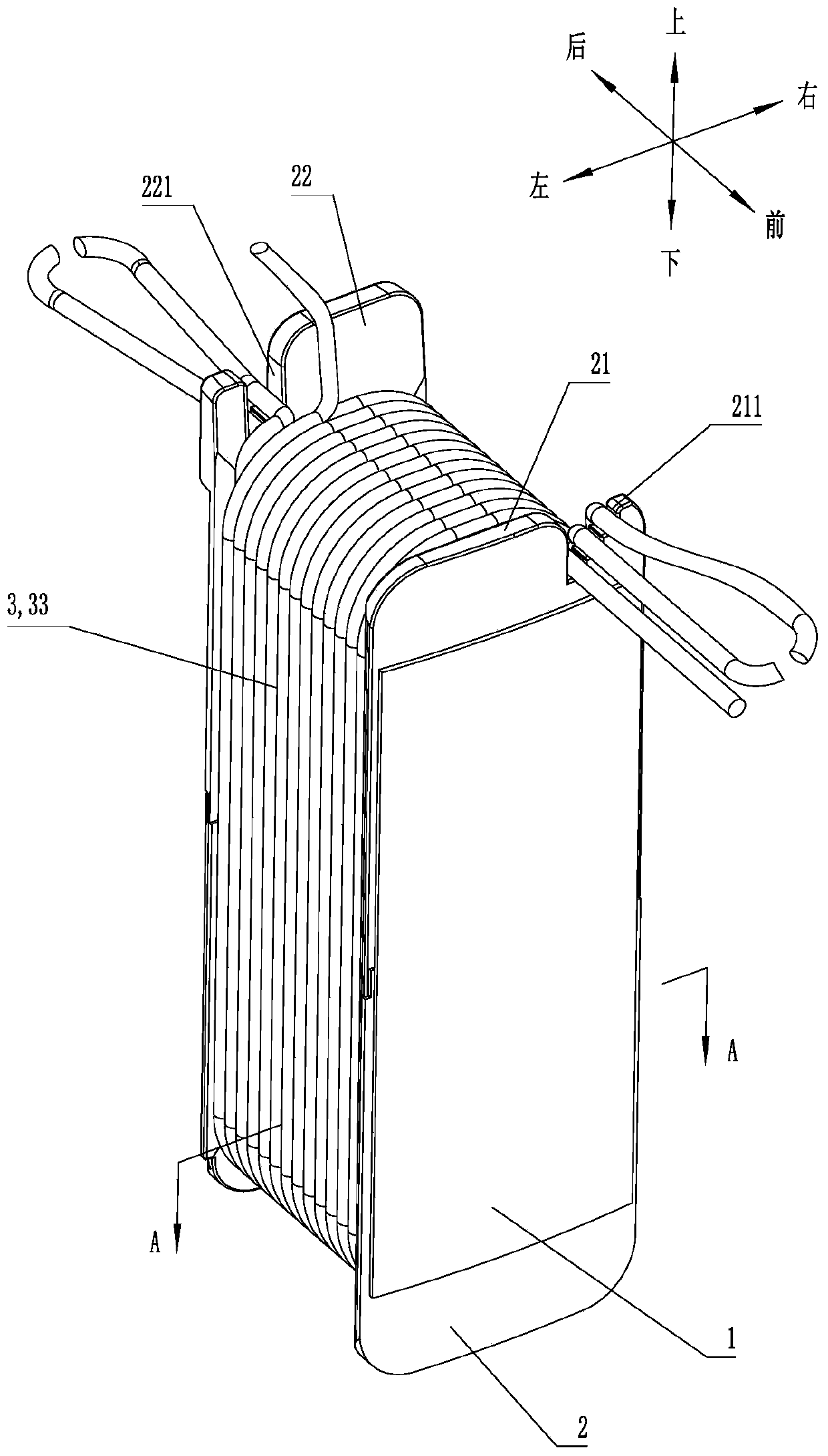
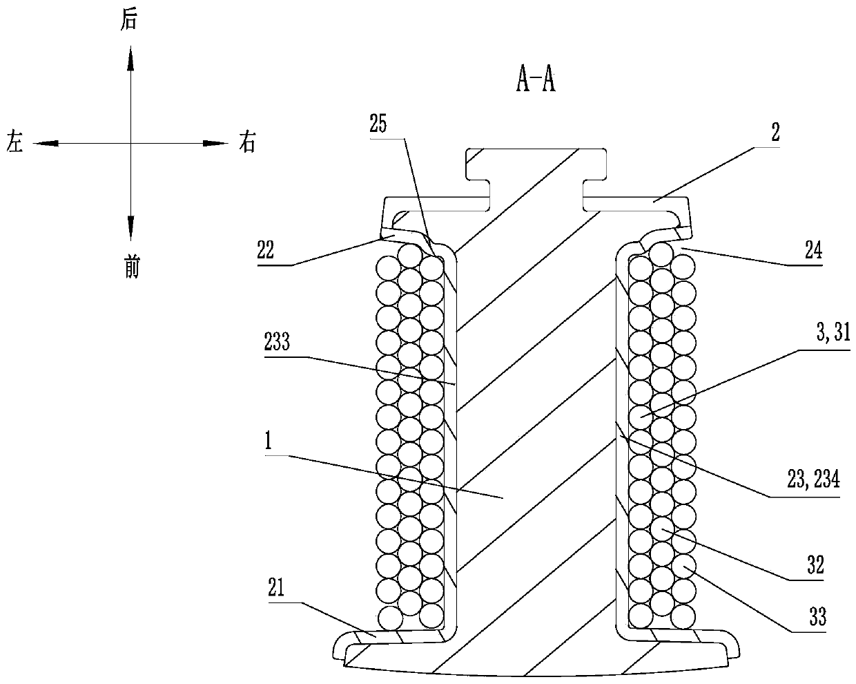
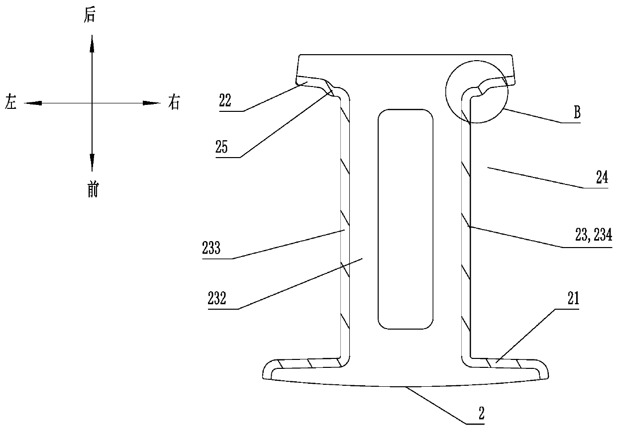
[0054] like Figure 1 to Figure 5 As shown, this embodiment discloses a stator tooth module, including a stator tooth 1, an insulating frame 2 and a winding 3, and the insulating frame 2 is sleeved on the stator tooth 1. In this embodiment, the insulating frame 2 is composed of an upper frame 2a and a The lower frame 2b is spliced ​​together, and the insulating frame 2 adopts a two-half split structure, which not only facilitates the manufacture of the insulating frame 2, thereby reducing the manufacturing cost of the insulating frame 2, but also greatly facilitates the assembly of the insulating frame 2 to the Stator tooth 1, thereby facilitating the manufacture of the stator tooth module and improving production efficiency. The two-half split structure of the insulating frame 2 is an existing conventional technology, so it will not be repeated here.

[0055] The insulating frame 2 is provided with a front fender 21, a rear fender 22, and a support sleeve 23 between the front...

Embodiment 2

[0066] like Figure 1 to Figure 6 As shown, this embodiment discloses a stator, including the stator yoke 4 and the stator tooth modules in Embodiment 1, all the stator tooth modules are evenly distributed on the outer periphery of the stator yoke 4 in the circumferential direction, and each stator tooth module The stator tooth 1 and the stator yoke 4 are detachably spliced ​​together. The detachable splicing structure of the stator tooth 1 and the stator yoke 4 is an existing conventional technology, so it will not be repeated here.

[0067] The stator in this embodiment is applied to a motor with an inner stator and an outer rotor structure. When the stator needs to be applied to a motor with an outer stator and an inner rotor structure, it is only necessary to distribute all the stator tooth modules evenly in the circumferential direction. The inner peripheral portion of the stator yoke 4 and each stator tooth module can be detachably spliced ​​together with the stator yoke...

Embodiment 3

[0069] like Figure 1 to Figure 6 As shown, this embodiment discloses a motor, including the stator in Embodiment 2.


PUM


Abstract

The invention relates to a stator tooth module. The stator tooth module comprises stator teeth, an insulation framework and a winding, wherein a winding groove is formed in the insulation framework, and the winding is wound in the winding groove; a vertical convex strip is arranged at each of the rear ends of the outer surfaces of a left supporting plate and a right supporting plate of a supporting sleeve; the first coil group of the winding is wound on the supporting sleeve between the vertical convex strip and a front baffle; the second coil group of the winding is wound on the first coil group; the coil at the last end in the second coil group is tightly pressed on the coil at the last end in the first coil group and a rear baffle plate and / or the vertical convex strip; and any other coil in the second coil group is tightly pressed on two adjacent coils in the first coil group. The invention further relates to a stator comprising the stator tooth module, a motor comprising the stator and a winding method for the winding in the stator tooth module. The invention has the advantages that the requirement for the winding machine is low, the manufacturing cost of the winding can be effectively reduced, the full rate of the motor groove is high, and the performance of the motor is good.

Description

technical field [0001] The invention relates to the field of motors, in particular to a stator tooth module, a stator, a motor and a winding winding method in the stator tooth module. Background technique [0002] For traditional motors, due to the limitation of slot openings on the one-piece stator, direct winding or embedding of windings is relatively difficult, and the slot fill rate is low and the manufacturing cost is high. In order to facilitate the winding of the winding and improve the motor slot full rate, some motors disassemble the stator into the stator yoke and multiple stator tooth modules, and the multiple stator tooth modules are evenly distributed on the outer or inner circumference of the stator yoke , all the stator tooth modules and the stator yoke are detachably connected together by a splicing structure. [0003] In order to facilitate the winding of the winding in the stator tooth module and increase the overcurrent capability of the winding, the wind...

Claims


Application Information

Patent Timeline
IPC IPC(8): H02K1/14H02K1/16H02K3/28H02K3/34H02K3/38H02K3/50H02K15/085
Inventor 冉建康罗玉龙周培良谭建华余宁管良围马国宏
Owner NINGBO SHENGLONG AUTOMOTIVE POWERTRAIN SYSTEM CO LTD
Learn More