Method for regulating rectifier output voltage for wireless electric energy transmission

A technology for wireless power transmission and output voltage, which is applied in the direction of converting AC power input to DC power output, output power conversion device, high-efficiency power electronic conversion, etc. Efficiency and other issues, to achieve the effect of high practicability, reduced loss, and reduced number of devices

Active Publication Date: 2019-05-14
甘肃南洋新能源科技发展有限公司
View PDF2 Cites 0 Cited by
  • Summary
  • Abstract
  • Description
  • Claims
  • Application Information

AI Technical Summary

Problems solved by technology

[0004] The purpose of the present invention is to solve the problem of low transmission efficiency caused by diode rectification loss at the wireless receiving end, and at the same time, the output voltage of diode rectification cannot be adjusted, which requires additional components, which reduces system efficiency and increases production costs. A method for regulating the output voltage of a rectifier for wireless power transfer

Method used


Image

  • Method for regulating rectifier output voltage for wireless electric energy transmission

Examples


Embodiment 1

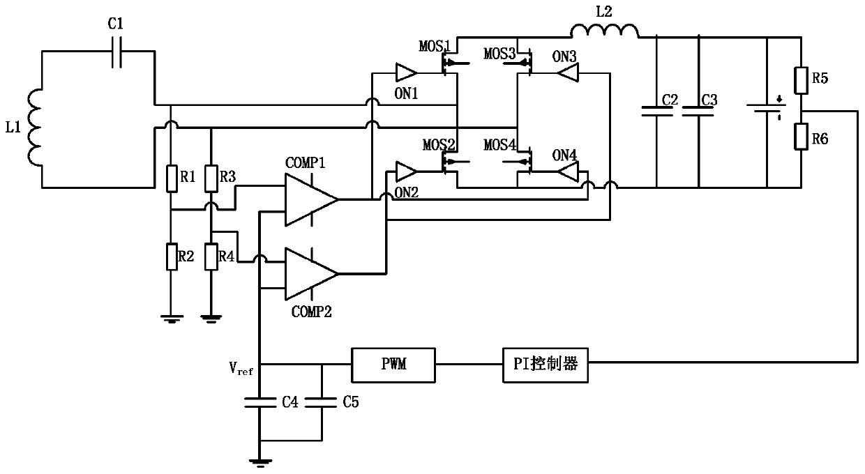
[0032] A method for adjusting the output voltage of a rectifier for wireless power transmission provided by a preferred embodiment of the present invention includes the following steps:

[0033] Step 1: Resistors R1 and R2, R3 and R4 collect the input voltage of the rectifier respectively, and the voltage collected by resistors R1 and R2 is recorded as V det1 , record the voltage collected by resistors R3 and R4 as V det2 , resistors R5 and R6 collect the output voltage of the rectifier; wherein, the rectifier includes a bridge rectifier composed of MOS tube 1, MOS tube 2, MOS tube 3, MOS tube 4 and corresponding MOS tube drive chips ON1, ON2, ON3, ON4 circuit and a synchronous signal detection circuit composed of resistors R1-R6, PI controller, PWM, voltage comparators COMP1, COMP2, capacitors C4 and C5.

[0034] Step 2: The PI controller adjusts the voltage threshold V according to the output voltage collected by resistors R5 and R6 ref , and then compare the acquisition v...

Embodiment 2

[0050] On the basis of Embodiment 1, the back end of the bridge rectifier circuit is also connected with a filter and voltage regulator circuit for stabilizing and filtering the output voltage. The connected inductor L2 and the capacitors C2 and C3 connected in parallel with the load can stabilize and filter the output voltage through the inductor L2, capacitors C2 and C3. The circuit is simple, the design is reasonable, and the practicability is high.


PUM


Abstract

The invention discloses a method for regulating a rectifier output voltage for wireless electric energy transmission, related to the technical field of wireless electric energy transmission. The method for regulating the rectifier output voltage for the wireless electric energy transmission comprises the following steps: 1, resistors R1 and R2, R3 and R4 separately collect the input voltage of therectifier, the voltages collected by the resistors R1 and R2 are recorded as V<det1>, the voltages collected by the resistors R3 and R4 are recorded as V<det2>, and resistors R5 and R6 collect the output voltage of the rectifier; wherein the rectifier comprises a MOS transistor 1, a MOS transistor 2, a MOS transistor 3, a MOS transistor 4, the resistors R1 to R6, a PI controller, a PWM, and voltage comparators COMP1 and COMP2; and 2, the PI controller adjusts a voltage threshold V<ref> according to the output voltages collected by the resistors R5 and R6, and compares the sizes of the collected voltages V<det1>, V<det2> and the current voltage threshold V<ref>; if V<det1> is greater than V<ref>, the voltage comparator COMP1 outputs a high level to turn on the MOS transistor 1 and the MOStransistor 4; and if V<det2> is greater than V<ref>, the voltage comparator COMP2 outputs a high level to turn on the MOS transistor 2 and the MOS transistor 3. According to the invention, through thecombination of synchronous rectification and phase shifting, the rectification loss is reduced and the production cost is reduced.

Description

technical field [0001] The invention relates to the technical field of wireless power transmission, in particular to a method for adjusting the output voltage of a rectifier for wireless power transmission. Background technique [0002] Wireless power transmission, also known as wireless power transmission, non-contact power transmission, refers to the conversion of electrical energy into other forms of relay energy through the transmitter, and after a distance is transmitted through the air, the relay energy is converted into electrical energy through the receiver to achieve Wireless power transmission. The wireless power transmission system includes a wireless transmitter and a wireless receiver that transmit energy through a magnetic field. The rectifier (rectifier) ​​at the wireless receiver is a device that converts alternating current into direct current. It can be used for power supply and radio signal detection. The rectifier can be made of vacuum tubes. , ignition ...

Claims


Application Information

Patent Timeline
IPC IPC(8): H02M7/219H02M1/14
CPCY02B70/10
Inventor 张华张永恒
Owner 甘肃南洋新能源科技发展有限公司
Why Eureka
Try Eureka