New energy electric first-aid trolley

A new energy, electric technology, applied in the field of machinery, can solve the problems of consuming the physical strength of medical staff, increasing the secondary injury of patients, etc., and achieve the effect of reducing work intensity, improving stability, and avoiding shaking

Pending Publication Date: 2019-05-17
QINGDAO MUNICIPAL HOSPITAL
View PDF10 Cites 0 Cited by
  • Summary
  • Abstract
  • Description
  • Claims
  • Application Information

AI Technical Summary

Problems solved by technology

[0004] The purpose of the present invention is to provide a new energy electric emergency trolley to solve the problem of consuming a lot of physical strength of the medical staff and increasing the risk of secondary injury of the patient during the transfer.

Method used


Image

  • New energy electric first-aid trolley
  • New energy electric first-aid trolley
  • New energy electric first-aid trolley

Examples


Embodiment 1

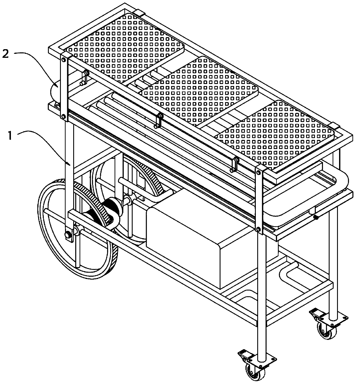
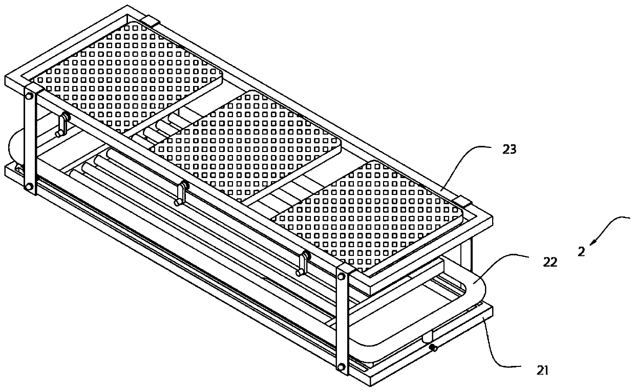
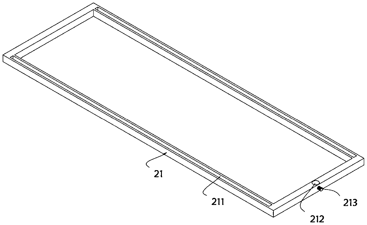
[0042] A new energy electric emergency cart, such as Figure 1-Figure 6 As shown, it includes a new energy electric emergency cart, including a car body 1 and a frame body 2 installed on the top of the car body 1. The frame body 2 is sequentially provided with a receiving frame 21, a moving frame 22 and a top frame from bottom to top. Frame 23, the top of receiving frame 21 is provided with chute 211, and one side of the top of receiving frame 21 is also provided with slot 212, and the outer wall of receiving frame 21 is equipped with positioning bolt 213 near slot 212 side, and one side of mobile frame 22 The bottom end is equipped with a connecting piece 221. The connecting piece 221 includes a lower hinge plate 2211 and an upper hinge plate 2213. A groove 2212 is opened inside the lower hinge plate 2211. The upper hinge plate 2213 and the lower hinge plate 2211 are connected by a rotating shaft 2214. The bottom of the lower hinge plate 2211 is equipped with a sliding post 2...

Embodiment 2

[0048] As a second embodiment of the present invention, in order to facilitate the collection of solar energy resources, the inventors arrange a plurality of solar panels 235 on the top frame 23, as a preferred embodiment, as Figure 7 As shown, a fixed plate 231 is installed between the top frame 23 and the mobile frame 22, the two ends of the fixed plate 231 are respectively provided with clamp feet 232, and the two ends of the fixed plate 231 are respectively provided with fastening screws 233, and the top frame 23 is installed There are a plurality of solar panels 235, and the two ends of the solar panels 235 are installed on the inner wall of the top frame 23 through the connecting shaft 234. The outer wall of the top frame 23 is provided with a plurality of crank handles 236, and the crank handle 236 and the connecting shaft 234 are coaxially arranged.

[0049] In this embodiment, the fixing plate 231 and the clamping feet 232 are integrally formed, and the clamping feet ...

Embodiment 3

[0054] As a third embodiment of the present invention, in order to facilitate the conversion of collected solar energy resources, the inventors improved the structure of the car body 1, as a preferred embodiment, such as Figure 8-10 As shown, an underframe 11 is installed on the bottom of the car body 1, and support columns 12 are respectively installed around the underframe 11, and universal wheels 13 are installed at the bottom of the support column 12 on one side of the car body 1, and on the other side of the car body 1. A drive wheel 14 is installed at the bottom of the support column 12, a drive motor 15 is installed between the two drive wheels 14, an electrical box 16 is provided on the underframe 11, and the support column 12 and the receiving frame 21 are welded and fixed.

[0055] In this embodiment, the electrical box 16 is provided with an inverter and a battery, and the solar panel 235 stores electric energy in the battery through the inverter.

[0056] Furtherm...


PUM


Abstract

The invention relates to the technical field of machinery, in particular to a new energy electric first-aid trolley which comprises a trolley body and a trolley frame body arranged at the top of the trolley body. A bearing frame, a movable frame and a top frame are sequentially arranged on the trolley frame body from bottom to top. According to the novel energy electric first-aid trolley, a sliding column slides in a sliding groove to draw out the movable frame, so that the movable frame can be conveniently erected in an ambulance box, a patient can be directly transferred to the movable framefrom the ambulance box, and injuries of the patient are decreased. In addition, operation is safe, time and labor are saved, electric energy is stored in a storage battery by a solar cell panel through an inverter, stable voltage is provided to a driving motor through the storage battery, and the driving motor works to drive driving wheels to rotate. The whole movement of the trolley body is achieved, new energy is used as driving energy, the requirements of energy conservation and environmental protection are met, and the working strength of medical personnel can be reduced.

Description

technical field [0001] The invention relates to the field of mechanical technology, in particular to a new energy electric emergency cart. Background technique [0002] The emergency trolley is a medical device used to quickly transfer patients on the ambulance to the hospital for treatment. [0003] However, when the existing ambulance transports the patient, the patient needs to be lifted from the ambulance first, and then the patient is placed on the ambulance. This method not only consumes a lot of physical strength of the medical staff, but also increases the Risk of secondary harm to the patient. In view of this, we propose a new energy electric emergency cart. Contents of the invention [0004] The purpose of the present invention is to provide a new energy electric emergency trolley to solve the above-mentioned background technology that consumes a lot of physical strength of the medical staff and at the same time increases the risk of secondary injury of the pat...

Claims


Application Information

Patent Timeline
Patent Type & Authority Applications(China)
IPC IPC(8): A61G1/02A61G1/04C30B33/10C30B31/08C30B33/12C23C16/34H01L31/18H01L31/042H02S20/30F24S30/425H02J7/35
CPCY02E10/50Y02E10/47Y02P70/50
Inventor 王松梅
Owner QINGDAO MUNICIPAL HOSPITAL
Why Eureka
Try Eureka