Automobile processing gluing machine based on visual tracking detection
A technology of visual tracking and gluing machine, which is applied in the direction of coating, liquid coating device on the surface, etc., can solve the problems of reduced production efficiency, inconvenient use, difficult to adjust the position, etc., to reduce the time of equipment downtime and adjust the process Simple, high-precision adjustment effect
- Summary
- Abstract
- Description
- Claims
- Application Information
AI Technical Summary
Problems solved by technology
Method used
Image
Examples
Embodiment 1
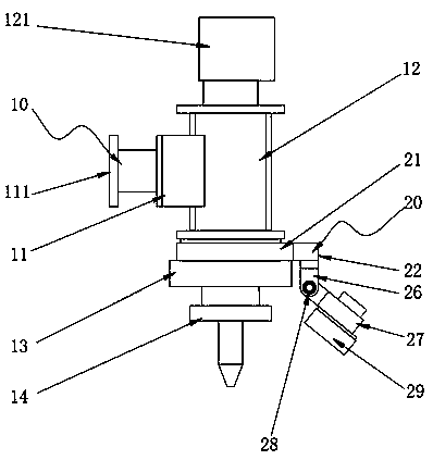
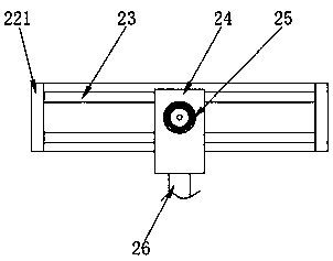
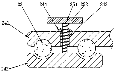
[0034] A glue applicator for automobile processing based on visual tracking detection, comprising a body assembly 10 and an adjustment assembly 20, the body assembly 10 includes a fixed seat 11, a glue bucket 12, a connecting seat 13 and a glue applicator 14, the glue bucket 12 and The fixed seat 11 is fixedly connected, the connecting seat 13 is fixedly connected to the bottom surface of the glue bucket 12, the glue applicator 14 is fixedly connected to the bottom surface of the connecting seat 13, and the adjustment assembly 20 includes a fixed block 21, an adjustment seat 22, a guide rod 23, and a sliding seat 24. Locking lever 25, connecting block 26, camera fixing seat 27, locking bolt 28 and industrial camera 29, fixing block 21 is fixedly connected to the outer wall of connecting seat 13, and adjusting seat 22 is fixedly connected to the side wall of fixing block 21, The guide rod 23 is fixedly connected with the fixed block 21, the sliding seat 24 is slidably connected ...
Embodiment 2
[0038] The difference between Embodiment 2 and Embodiment 1 is that the locking rod 25 includes a runner 251 and a screw rod 252, the runner 251 is fixedly connected to the top of the screw rod 252, and the screw rod 252 is threadedly connected with the internal thread 243, and is away from the runner 251 One end of one end is rotatably connected with the lower clamping plate 242, and the screw rod 252 is rotated by the runner 251, so that the upper clamping plate 241 and the lower clamping plate 242 interact to clamp the guide rod 23 to realize the fixing of the relative position.
Embodiment 3
[0040] Embodiment 3 differs from Embodiments 1 and 2 in that: the end of the connecting block 26 away from the sliding seat 24 is provided with a cantilever 261, the inner walls of the cantilever 261 are provided with a first anti-slip surface 262, and the camera fixing seat 27 is far away from the industrial camera 29 One end of the rotating arm 271 is fixedly connected with a rotating arm 271, and the two walls of the rotating arm 271 are provided with a second anti-skid surface 272. The cantilever 261 and the rotating arm 271 are rotatably connected by a locking bolt 28. By rotating the locking bolt 28, the cantilever 261 can be clamped and rotated. arm 271, so that the relative position of the connecting block 26 and the camera holder 27 is fixed; the first anti-slip surface 262 and the second anti-slip surface 272 are all arranged around the rotation center of the cantilever 261 and the rotating arm 271, when the cantilever 261 clamps the rotating arm 271, the second An an...
PUM
 Abstract
Description
Claims
Application Information
 - R&D
- Intellectual Property
- Life Sciences
- Materials
- Tech Scout
- Unparalleled Data Quality
- Higher Quality Content
- 60% Fewer Hallucinations
Browse by: Latest US Patents, China's latest patents, Technical Efficacy Thesaurus, Application Domain, Technology Topic, Popular Technical Reports.
© 2025 PatSnap. All rights reserved.Legal|Privacy policy|Modern Slavery Act Transparency Statement|Sitemap|About US| Contact US: help@patsnap.com


