
Water drainage type prefabricated pile convenient to construct and construction method of water drainage type prefabricated pile

A technology of prefabricated piles and pile bodies, applied in the fields of geotechnical, pile foundation and construction, can solve the problems of rigid piles that cannot be drained and the strength of bulk material piles is insufficient, and achieves the effect of improving vertical bearing capacity and enhancing lateral friction resistance.

Active Publication Date: 2019-05-17
上海民航新时代机场设计研究院有限公司
View PDF11 Cites 0 Cited by
  • Summary
  • Abstract
  • Description
  • Claims
  • Application Information

AI Technical Summary

Problems solved by technology

Solve the limitations of insufficient strength of bulk material piles and inability of rigid piles to drain water during the reinforcement process of liquefied foundation soil

Method used


Image

  • Water drainage type prefabricated pile convenient to construct and construction method of water drainage type prefabricated pile
  • Water drainage type prefabricated pile convenient to construct and construction method of water drainage type prefabricated pile
  • Water drainage type prefabricated pile convenient to construct and construction method of water drainage type prefabricated pile

Examples


Embodiment 1

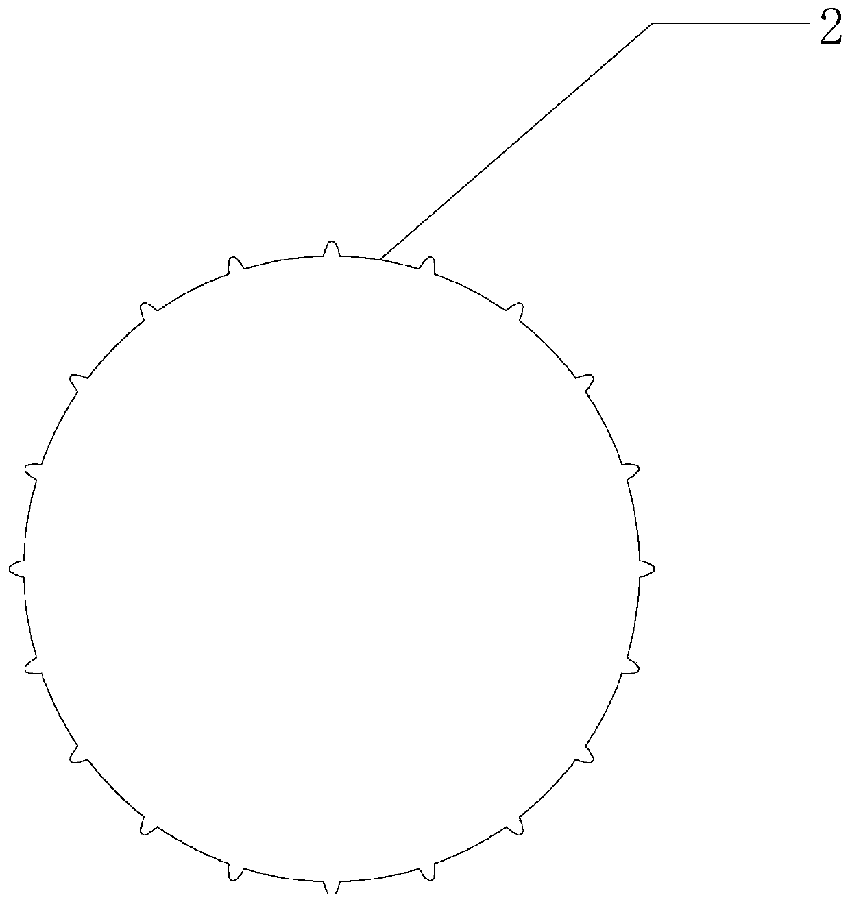
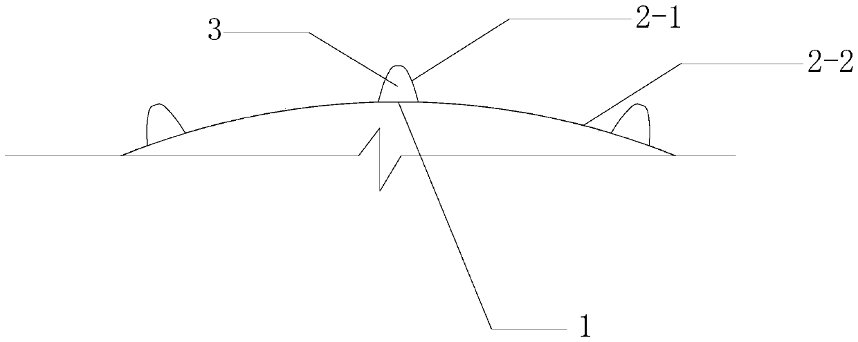
[0052] Embodiment 1: A self-draining prefabricated pile, comprising: an inner pile body 1 and an outer casing 2; the inner pile body 1 is prefabricated reinforced concrete, and its shape is circular.

[0053] The outer casing 2 is divided into: a protruding part 2-1, a matching part 2-2, the matching part 2-2 is adapted to the shape of the inner pile body 1, and several vertically extending protrusions 2-1 are arranged on the outer casing 2 , the protrusion space 3 formed between the protrusion 2-1 of the outer casing 2 and the inner pile body 1 serves as a vertical drainage channel.

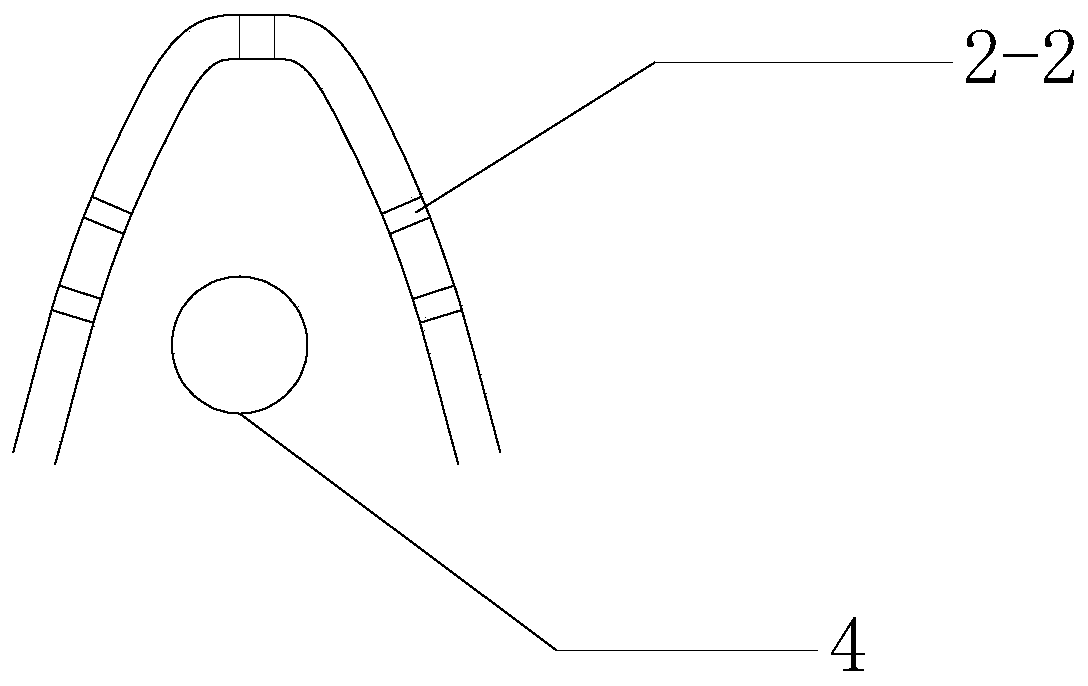
[0054] A number of permeable holes 2-2 are provided on the protrusion 2-1, so as to allow moisture to penetrate into the protrusion space 3 from the protrusion 2-1;

[0055] The matching part 2-2 is in contact with the inner pile body 1 .

[0056] The protrusions 2-1 of the outer case 2 are uniformly arranged.

[0057] A water suction pipe 4 is arranged in each raised space, and the water suctio...

Embodiment 2

[0072] Embodiment two: if Figure 6-7 As shown, the inner pile body 1 is rectangular, and the outline of the outer casing 2 is also rectangular. The outer casing 2 is divided into: a protrusion 2-1, a matching portion 2-2, and the matching portion 2-2 is connected with the inner pile body 1. The shape is adapted, and the outer shell 2 is provided with several vertically extending protrusions 2-1, and the protrusion space 3 formed between the protrusions 2-1 of the outer shell 2 and the inner pile body 1 serves as a vertical drainage channel; the protrusions 2-1 is provided with a number of permeable holes 2-2, so that water can penetrate into the protrusion space 3 from the protrusion 2-1; the matching part 2-2 is in contact with the inner pile 1; the protrusion 2-1 of the outer shell 2 Set multiples on each side of the rectangle;

[0073] The bottom of the internal pile body 1 is provided with a pile point 5, and the bottom of the internal pile body 1 is provided with an ann...


PUM


Abstract

The invention discloses a water drainage type prefabricated pile convenient to construct and a construction method of the water drainage type prefabricated pile. The water drainage type prefabricatedpile has the design points of comprising an inner pile, an outer shell and a pile tip, wherein the outer shell comprises a protruding part and a matching part; the matching part is adaptive to the shape of the inner pile; the internal shell is provided with a plurality of bulges which extend vertically; a protruding space formed between the bulges of the outer shell and the inner pile is used as an upright water drainage channel; a plurality of water permeation holes are formed in the protruding part, and then water can infiltrate into the protruding space from the protruding part; the pile tip is arranged at the lower part of the inner pile; an annular protruding platform is arranged at the lower part of the inner pile; the pile tip is a circular cone body; an annular groove matched withthe protruding platform in a radial direction is arranged at the upper part of the pile tip; spiral bulges which rise in an inclined direction are formed outside the pile tip. By adopting the water drainage type prefabricated pile convenient to construct and the construction method of the water drainage type prefabricated pile, a function of preventing ambient pile soil from liquidation under an earthquake working condition is achieved, and easiness in construction is achieved.

Description

technical field [0001] The invention relates to the fields of rock and soil, construction, pile foundation and the like, in particular to a drainage type prefabricated pile which is convenient for construction and a construction method thereof. Background technique [0002] CN206655217U discloses a prefabricated concrete drainage pile, comprising a prefabricated permeable concrete pipe, the top of the prefabricated permeable concrete pipe is provided with an overflow tank, the bottom of the overflow tank is connected with a vertical drainage channel, and the drainage channel is connected with the outside world, and the prefabricated permeable concrete pipe The outside is covered with a concrete sleeve, and the bottom of the concrete sleeve is a slope. The prefabricated permeable concrete pipe is installed with a prefabricated concrete pile core. The bottom of the prefabricated concrete pile core is integrally formed with a conical core tip. The inner diameter of the core tip...

Claims


Application Information

Patent Timeline
IPC IPC(8): E02D5/30E02D3/10
Inventor 郑秀平
Owner 上海民航新时代机场设计研究院有限公司
Learn More