Lever synergism power generation device

A power generation device and lever technology, applied in hydropower, engine components, machines/engines, etc., can solve the problems of small water tank volume and limited height, difficulties in wind power generation, and immature technology for improving efficiency, etc., to achieve the goal of increasing power generation efficiency Effect

Pending Publication Date: 2019-05-17
栗丰科
View PDF0 Cites 0 Cited by
  • Summary
  • Abstract
  • Description
  • Claims
  • Application Information

AI Technical Summary

Problems solved by technology

[0003] Although hydropower generation does not require raw materials like thermal power and nuclear power generation, in terms of water resources, it is not as easy as imagined to ensure sufficient water sources throughout the year. The same is true for wind power generation. After the monsoon season, the wind is extremely weak. At present, wind power generation is also very difficult. In addition, the scale of power station construction and the output power are relatively large. It is feasible to use the rotation principle of the waterwheel to generate electricity, because the rotation of the waterwheel can also drive the rotor of the generator to rotate.
[0004] However, in the existing field, the efficacy and ability of using waterwheels to generate electricity are all applied to the field of large rivers, and the volume of a single water tank on the waterwheel is small and the height is limited, and the volume of each water tank filled with water is small. effect, the technology for efficiency improvement in this field is not mature enough

Method used


Image

  • Lever synergism power generation device
  • Lever synergism power generation device
  • Lever synergism power generation device

Examples


specific Embodiment 1

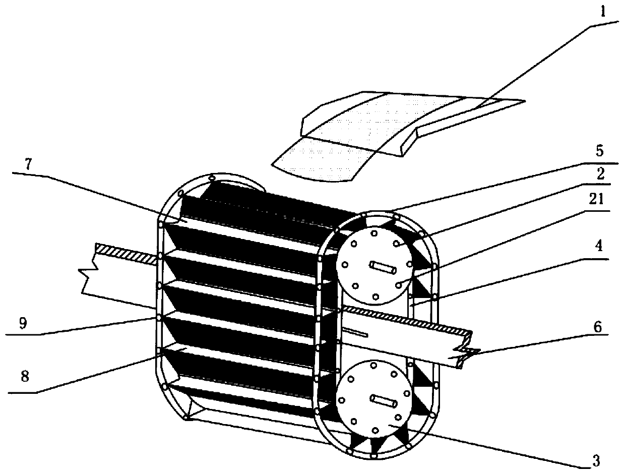
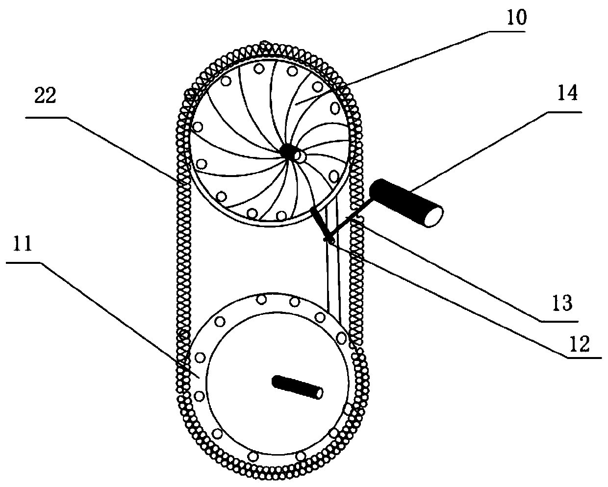
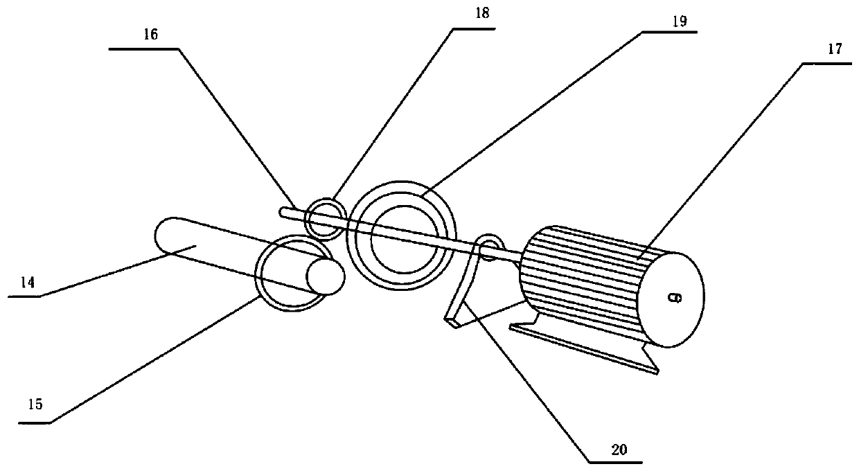
[0033] Such as figure 1 Shown, a kind of leverage synergistic power generation device, described device is made up of main power equipment group, lever group, transmission chain, variable speed and power generation group, and described main power equipment group is provided with and includes water source canal 1 and waterwheel, and described waterwheel The upper power wheel 2, the lower power wheel 3, the inner track 4, and the outer annular track 5 are symmetrically arranged on the left and right, and the upper power wheel 2 and the lower power wheel 3 are connected by the inner track 4 gears, and the inner track 4 and A number of water storage tanks 8 are evenly connected between the outer circular tracks 5, and the water storage tanks 8 are spliced ​​by chain plates 7, and the chain plates 7 are movably connected with movable casters arranged on the inner track 4 and the outer circular track 5. , the central cavity between the upper power wheel 2 and the lower power wheel 3...

specific Embodiment 2

[0039]On the basis of embodiment 1, a kind of leverage synergistic power generation device, described device is made up of main power equipment group, lever group, transmission chain, variable speed and generating set, and described main power equipment group is provided with and includes water source canal 1 and waterwheel , the left and right symmetry of described waterwheel is provided with upper power wheel 2, lower power wheel 3, inner side rail 4, outer ring track 5, between described upper power wheel 2 and lower power wheel 3 are connected by inner side track 4 gears, so A number of water storage tanks 8 are evenly connected between the inner track 4 and the outer circular track 5, and the water storage tanks 8 are spliced ​​by chain plates 7, and the chain plates 7 are arranged on the inner track 4 and the outer circular track 5 The movable casters are movably connected, and the central cavity between the upper power wheel 2 and the lower power wheel 3 is provided with...

specific Embodiment 3

[0042] On the basis of Embodiment 1, the transmission chain 22 can also be replaced by a transmission belt.


PUM


Abstract

The invention discloses a lever synergism power generation device. The lever synergism power generation device is characterized in that the device comprises a main power equipment group, a lever group, a transmission chain, a speed change part and a power generation group; the main power equipment group comprises a water source channel and a water wagon, and the water wagon is composed of an upperpower wheel, a lower power wheel, an inner-side rail, an outer-side circular rail, a load-bearing pole, a chain plate, a water storage groove and movable casters. The new device is mainly used for development and utilization of water resources of various small rivers in China; and an existing water wagon power generation structure can be reasonably improved, and the new device developed and usedby using water energy and green distributed energy fills the field of the development of the water resources of the small rivers.

Description

technical field [0001] The invention relates to the field of power generation devices, in particular to a lever synergistic power generation device. Background technique [0002] The current forms of power generation are roughly divided into thermal power, hydropower, wind power, nuclear power, etc. These types of power generation have their own advantages and disadvantages, and the daily maintenance costs are also high, and the operating cost is naturally high. Using fossil fuels to generate electricity pollutes the environment. Seriously, it consumes a lot of resources. In these power plants, they try to use all kinds of energy to rotate the rotor in the generator to generate electricity, so power generation requires energy to drive the rotor to rotate. Some sources of this energy are the combustion of fossil fuels, and wind power Power generation is subject to geographical and natural environment restrictions, and water conservancy power generation is also subject to geo...

Claims


Application Information

Patent Timeline
Patent Type & Authority Applications(China)
IPC IPC(8): F03B13/00F03B11/00F03B7/00
CPCY02E10/20
Inventor 栗丰科
Owner 栗丰科
Why Eureka
Try Eureka