

Heat pipe, manufacturing method of heat pipe and equipment comprising heat pipe
A heat pipe and equipment technology, applied in the field of heat conduction, can solve problems such as easy bonding, and achieve the effects of reducing barriers, enriching technical means, and flexible methods
- Summary
- Abstract
- Description
- Claims
- Application Information
AI Technical Summary
Problems solved by technology
Method used
Image


Examples
Embodiment 1
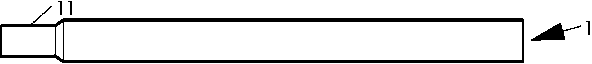
[0048] Step A: If figure 1 As shown, one end of the shell 1 is reduced in diameter to form a reduced head 11, and the other end is a tail. You can choose to chamfer the inner or outer corners at both ends of the shell 1 .
[0049] Step B: Combine figure 2 Combining the metal mesh 2 with the tube shell 1, the outer diameter of the metal mesh 2 matches the inner diameter of the shrinking head 11, and the shrinking head 11 and the metal mesh 2 are fixed by welding.
[0050] Step C: Combine image 3 , Combining the mandrel 3, the auxiliary metal mesh 2 and the inner wall of the shell 1 maintain a relatively uniform gap 4 to facilitate powder filling; fill the gap 4 with an appropriate amount of metal powder, and then separate the mandrel 3 from other elements.
[0051] Step D: put the workpiece obtained in the previous step into a sintering furnace, and perform sintering under the protection and reduction of protective gas and reducing atmosphere. After cooling, get as Fig...
Embodiment 2
[0079] In Example 1, a process route that can realize bending (flattening) first and then sintering has been given. Obviously, the manufacturing method of heat pipes and the manufacturing process of heat pipe radiators with various common structures can be more comprehensively combination. Although this embodiment can better integrate the manufacturing methods of heat pipes and heat pipe radiators compared with Document 17, it does not mean that all heat pipe radiators included in the present invention are manufactured by such methods. Generally speaking, this In the invention, the heat pipe is firstly used as a finished product, and then the heat pipe radiator is made by adopting the prior art. This embodiment is mainly to provide a different manufacturing method of the heat pipe radiator.
[0080] combine Figure 7 and 8 , taking the common (tower CPU) radiator 7 as an example, generally the tube shell 1 filled with powder in Example 1 is shrunk and welded, and then bent ...
Embodiment 3
[0087] combine Figure 9 First, the left end of the shell 1 is sealed and welded, and then the metal mesh 2, the mandrel 3, the funnel 6, and the shell 1 are combined, filled with powder, and the metal powder enters the gap 4 from the gap between the positioning blocks 62. If the wire mesh 2 comprises a wound wire mesh, the wire mesh can optionally be wound on the mandrel 3 .
[0088] After filling the powder, remove the positioning tooling. If the mandrel 3 is separated earlier, then the funnel 6 is fixed, and the positioning block 62 and the end face 63 of the funnel 6 can block the metal mesh 2 and prevent it from moving. If the funnel 6 is separated earlier, the mandrel 3 is inserted into the mandrel 3 with a washer (used in conjunction with the bolt) to block the metal mesh 2, and the mandrel 3 is extracted.
[0089] A workpiece containing metal powder is sintered and then other processes are performed.
[0090]In particular, after the mandrel 3 is separated, a small a...
PUM
| Property | Measurement | Unit |
|---|---|---|
| Wall thickness | aaaaa | aaaaa |
| Thickness | aaaaa | aaaaa |
| Particle size | aaaaa | aaaaa |
Abstract
Description
Claims
Application Information