
Microstrip antenna structure and method for radiating electromagnetic signals

A microstrip antenna, electromagnetic wave signal technology, applied in the direction of antenna grounding switch structure connection, antenna, antenna array, etc., can solve the problems of narrow bandwidth, long contact length, low transmission efficiency of microstrip antenna, etc., to improve transmission efficiency and bandwidth , the effect of low cost

Inactive Publication Date: 2019-05-17
北京木牛领航科技有限公司
View PDF2 Cites 3 Cited by
  • Summary
  • Abstract
  • Description
  • Claims
  • Application Information

AI Technical Summary

Problems solved by technology

In the traditional microstrip antenna, since the electromagnetic signal passes through each array element, a certain amount of energy will be emitted, and the contact length of each array element is longer, resulting in low emission efficiency and narrow bandwidth of the microstrip antenna with this structure.

Method used


Image

  • Microstrip antenna structure and method for radiating electromagnetic signals
  • Microstrip antenna structure and method for radiating electromagnetic signals
  • Microstrip antenna structure and method for radiating electromagnetic signals

Examples


Embodiment Construction

[0037] The following will clearly and completely describe the technical solutions in the embodiments of the present invention with reference to the accompanying drawings in the embodiments of the present invention. Obviously, the described embodiments are only some of the embodiments of the present invention, not all of them. Based on the embodiments of the present invention, those skilled in the art can make various changes and substitutions, and all other obtained embodiments fall within the protection scope of the present invention.

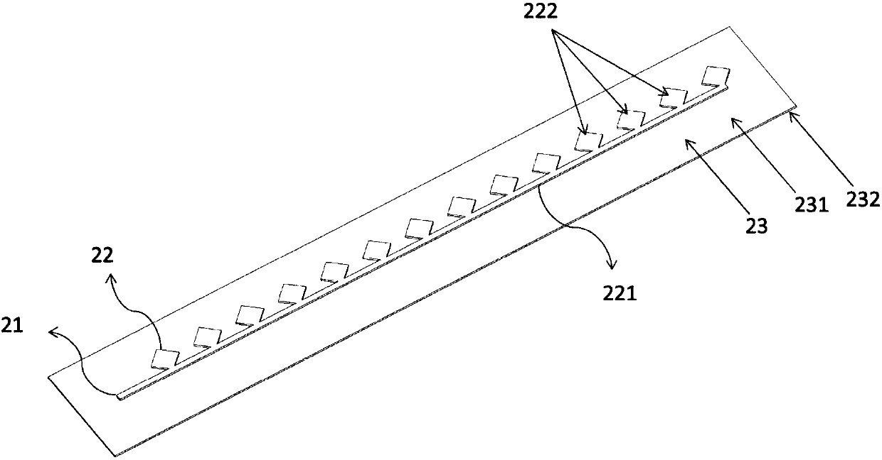
[0038] Generally speaking, the microstrip line is an antenna formed by pasting a conductive sheet on a dielectric substrate with a conductive ground plate on the back. Usually, a microstrip transmission line or a coaxial probe is used to feed power, so that a high-frequency electromagnetic field is excited between the conductor patch and the ground plate, and radiates outward through the gap between the patch and the ground plate. The metal pa...


PUM


Abstract

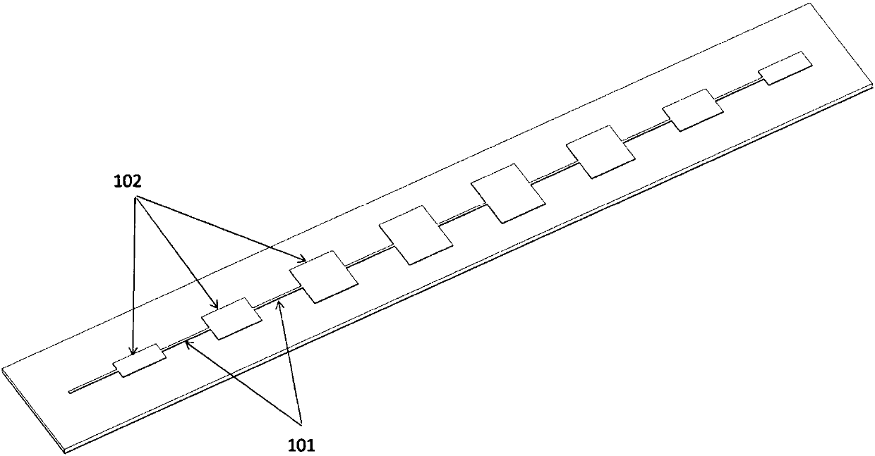
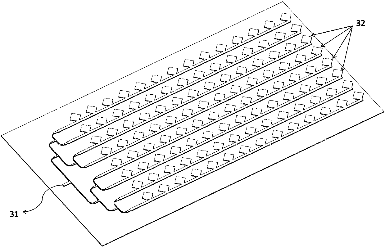
The invention provides a microstrip antenna structure and a method for radiating electromagnetic signals. The microstrip antenna structure comprises a signal input unit, a signal radiation unit, a grounding unit and a dielectric substrate unit. The signal input unit is used for inputting electromagnetic wave signals. The signal radiation unit is connected with the signal input unit and is used forreceiving and radiating the electromagnetic wave signals into space, and comprises a microstrip line and a plurality of antenna array elements, wherein the antenna array elements are distributed at equal intervals along the microstrip line, and the length of the microstrip line penetrating through the antenna array elements is smaller than the short sides of the antenna array elements. The grounding unit is used for forming a radio frequency ground. The dielectric substrate unit is provided with a first surface and a second surface opposite to the first surface, the signal input unit and thesignal radiation unit are located on the first surface, and the grounding unit is located on the second surface. According to the microstrip antenna structure and the method for radiating the electromagnetic signals, the contact length of the electromagnetic signals between the microstrip lines and the antenna array elements is reduced, and the antenna transmission efficiency and bandwidth are improved.

Description

technical field [0001] The invention belongs to the technical field of radar antennas, in particular to a microstrip antenna structure and a method for radiating electromagnetic signals. Background technique [0002] Radar has been widely used in various detections. The basic task is to detect the target and measure the state parameters such as the distance, direction and angle of the target. The radar includes an antenna, a transmitter and a receiver. The transmitter generates enough electromagnetic energy and transmits it through the transceiver switch. For the antenna, the antenna radiates the electromagnetic energy into the atmosphere, concentrates it in a very narrow direction to form a beam, and propagates forward. After the electromagnetic wave encounters the target in the beam, it will be reflected in all directions, and part of the electromagnetic energy Reflected back to the direction of the radar, it is acquired by the radar antenna, and the energy acquired by the...

Claims


Application Information

Patent Timeline
Patent Type & Authority Applications(China)
IPC IPC(8): H01Q21/00H01Q1/38H01Q1/48H01Q1/50
Inventor 王宗博冀连营
Owner 北京木牛领航科技有限公司
Learn More