Supercharge Your Innovation With Domain-Expert AI Agents!

Permanent magnet rotor assembly and motor

A technology for permanent magnet rotors and components, applied in the direction of magnetic circuit rotating parts, magnetic circuit shape/style/structure, etc., can solve the problems of weak combination of magnetic block and permanent magnet, low production efficiency, poor injection quality, etc. Achieve the effects of not easy to deform, high production efficiency and good injection quality

Pending Publication Date: 2019-05-17
ZHONGSHAN BROAD OCEAN
View PDF0 Cites 5 Cited by
  • Summary
  • Abstract
  • Description
  • Claims
  • Application Information

AI Technical Summary

Problems solved by technology

[0004] The purpose of the present invention is to provide a permanent magnet rotor assembly and a motor to solve the problem of poor injection molding quality, low production efficiency and high scrap rate caused by the weak combination of the magnetic block and the permanent magnet of the permanent magnet rotor assembly in the prior art question

Method used


Image

  • Permanent magnet rotor assembly and motor
  • Permanent magnet rotor assembly and motor
  • Permanent magnet rotor assembly and motor

Examples


Embodiment 1

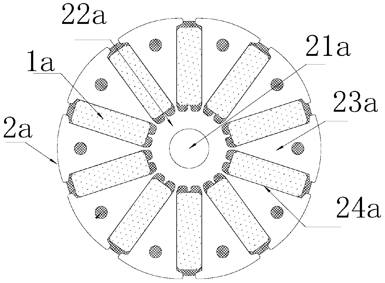
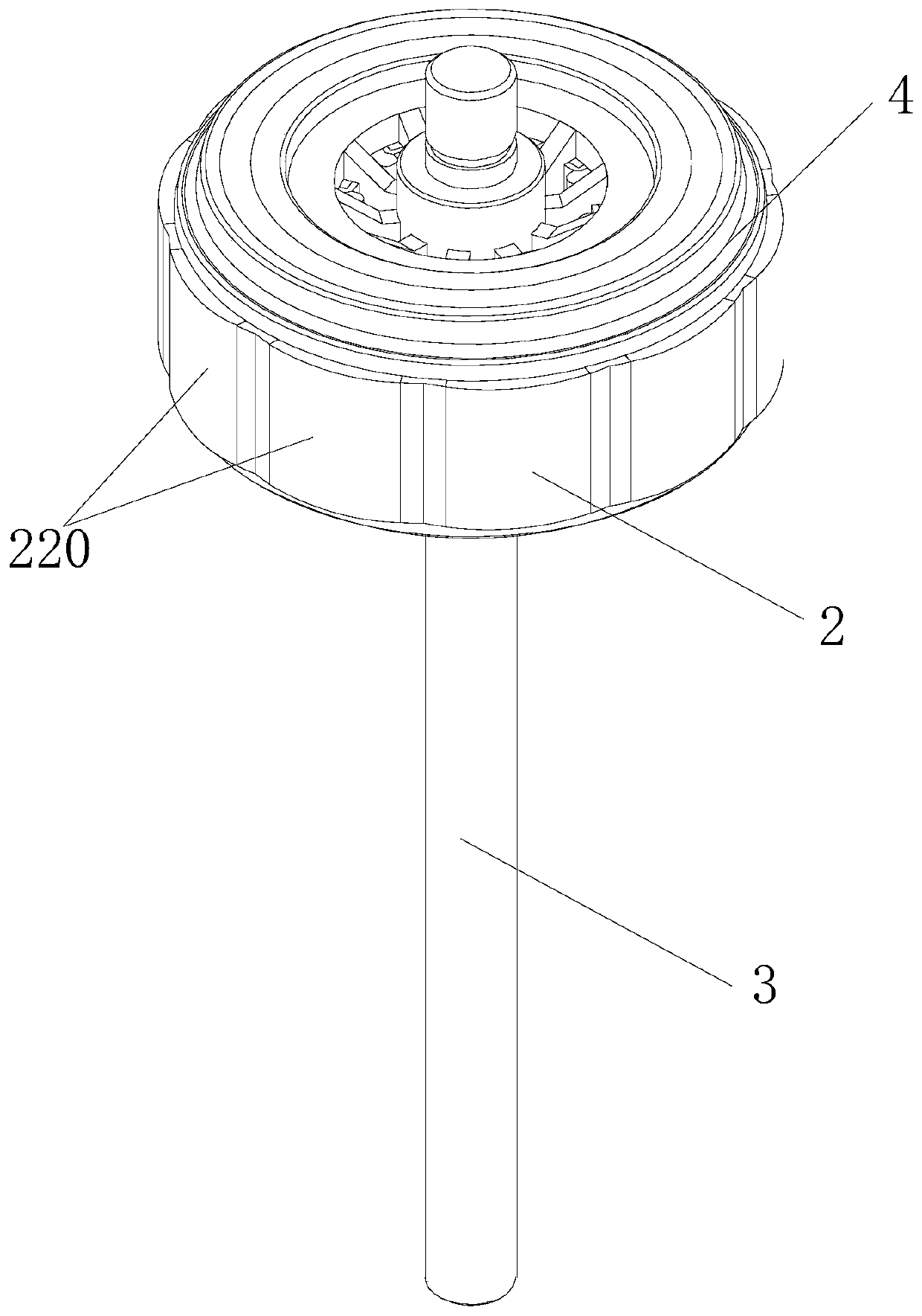
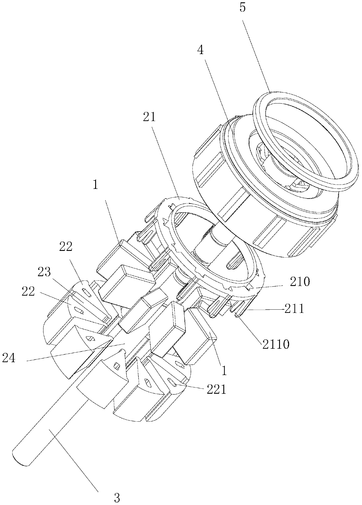
[0030] Example 1: as Figure 2 to Figure 9 As shown, the present invention is a permanent magnet rotor assembly, including a plurality of permanent magnets 1, a rotor iron core assembly 2, a rotating shaft 3 and a plastic sealing body 4, and the rotor iron core assembly 2 includes a mounting bracket 21 and a number of magnetic conductive blocks 22, so The above-mentioned mounting bracket 21 includes an annular end plate 210 and a plurality of clamping blocks 211 axially protruding from one end face of the annular end plate 210. The plurality of clamping blocks 211 are distributed around the annular end plate 210 at intervals. , a plurality of magnetic conductive blocks 22 are installed through the cooperation of the clamping block 211 and the card slot 221 to form a central hole 24, a radial groove 23 is formed between two adjacent magnetic conductive blocks 22, and the permanent magnet 1 is nested in the radial groove. Inside the groove 23 , the rotating shaft 3 passes throug...

Embodiment 2

[0038] This embodiment provides a motor, which includes a stator assembly, a permanent magnet rotor assembly and a motor housing, and is characterized in that: the permanent magnet rotor assembly is the permanent magnet rotor assembly described in the first embodiment.


PUM


Abstract

The invention discloses a permanent magnet rotor assembly and a motor. The permanent magnet rotor assembly comprises a plurality of permanent magnets, a rotor core assembly, a rotating shaft and a plastic-encapsulated body, the rotor core assembly comprises a mounting bracket and a plurality of magnetic conductive blocks, the mounting bracket comprises an annular end plate and a plurality of clamping blocks axially raised from one end surface of the annular end plate, a plurality of clamping blocks are distributed at intervals around the annular end plate, a clamping slot is formed in each magnetic conductive block, a plurality of magnetic conductive blocks are mounted by virtue of fit of the clamping blocks and the clamping slots and form a center hole, a radial groove is formed between every two adjacent magnetic conductive blocks, the permanent magnets are nested in the radial grooves respectively, the rotating shaft passes through the center hole, and the plastic-encapsulated bodyplastically encapsulates the rotating shaft, a plurality of permanent magnets, the mounting bracket and a plurality of magnetic conductive blocks into a whole. The permanent magnet rotor assembly disclosed by the invention fixes a plurality of magnetic conductive blocks and a plurality of permanent magnets by utilizing the mounting bracket, the whole structural strength is good, deformation is hardly caused, injection moulding quality is good, production efficiency is high, and rejection rate is extremely low.

Description

Technical field: [0001] The invention relates to a permanent magnet rotor assembly and a motor. Background technique: [0002] like figure 1 As shown, the conventional permanent magnet rotor assembly includes: a permanent magnet 1a and a rotor core 2a, the rotor core 2a includes an annular ring 22a provided with a central shaft hole 21a and a number of magnetic conductive blocks protruding from the outside of the annular ring 22a 23a, a radial groove 24a is formed between two adjacent magnetic conductive blocks 23a, and the permanent magnet 1a is embedded in the radial groove 24a. This structure has the following disadvantages: 1) the rotating shaft is installed in the central shaft hole 21a, and the rotating shaft is rigidly connected with the annular ring 22a, resulting in poor shock absorption; 2) the rotor core 2a has a large diameter, many consumables, and heavy weight, resulting in high cost. [0003] In view of this, in order to solve the existing technical problems...

Claims


Application Information

Patent Timeline
IPC IPC(8): H02K1/27H02K1/30
Inventor 潘明攀梁三增李泽凯
Owner ZHONGSHAN BROAD OCEAN
Features
  • R&D
  • Intellectual Property
  • Life Sciences
  • Materials
  • Tech Scout
  • Unparalleled Data Quality
  • Higher Quality Content
  • 60% Fewer Hallucinations
Learn More