Supercharge Your Innovation With Domain-Expert AI Agents!

Control method for realizing low quiescent current in switch buck converter

A technology of quiescent current and control method, which is applied in the direction of converting DC power input to DC power output, control/regulation systems, instruments, etc. The effect of low static power consumption and improved integration

Active Publication Date: 2019-05-17
钰泰半导体股份有限公司
View PDF4 Cites 2 Cited by
  • Summary
  • Abstract
  • Description
  • Claims
  • Application Information

AI Technical Summary

Problems solved by technology

However, this method needs to add an additional loop other than the voltage regulation loop of the output voltage itself, so that the output voltage cannot automatically or seamlessly enter the through low current mode or exit from the through low current mode, thus making the The output voltage will produce a relatively large ripple (such as image 3 shown)

Method used


Image

  • Control method for realizing low quiescent current in switch buck converter
  • Control method for realizing low quiescent current in switch buck converter
  • Control method for realizing low quiescent current in switch buck converter

Examples


Embodiment Construction

[0042] Below in conjunction with the drawings, preferred embodiments of the present invention are given and described in detail.

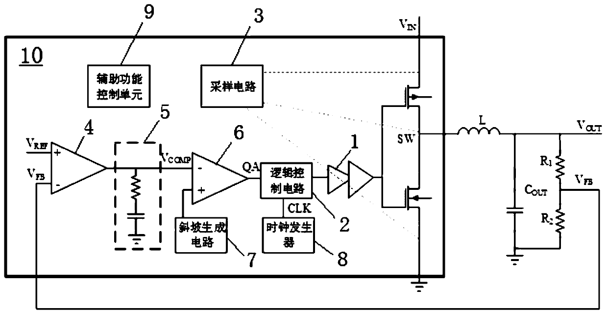
[0043] In the present invention, that is, a control method for realizing low quiescent current in a switching buck converter, the specific structure of the switching buck converter involved can be as follows figure 1 Shown (no longer go into details here); Method of the present invention comprises the following steps:

[0044] Step S0, according to the output signal QA of the PWM comparator 6 and the state of the PMOS power transistor PM within a predetermined time, it is judged that the peak current mode control chip 10 enters the switch frequency hopping mode or the direct low current mode;

[0045] Specifically, in step S0, when the output signal QA of the PWM comparator 6 is at a high level, regardless of whether the state of the PMOS power transistor PM is on or off, the peak current mode control chip 10 enters the switch frequency hopping mod...


PUM


Abstract

The invention relates to a control method for realizing a low quiescent current in a switch buck converter. The control method comprises the steps that according to an output signal of a PWM comparerand the state of a PMOS power tube in predetermined time, whether a peak current mode control chip gets into a switch frequency-hopping mode or a through low-current mode is judged; when the peak current mode control chip works in the switch frequency-hopping mode, if the switch buck converter is in an underloaded state, unnecessary power consumption modules in the peak current mode control chip are shut down; and when the peak current mode control chip works in the through low-current mode, unnecessary power consumption modules in the peak current mode control chip are shut down. Through thecontrol method, the peak current mode control chip in the switch buck converter can seamlessly and automatically switch between the switch frequency-hopping mode and the through low-current mode, andtherefore the switch buck converter has an extremely low quiescent current within a full input voltage range and maintains extremely low quiescent power consumption.

Description

technical field [0001] The invention relates to a switch step-down converter (Buck), in particular to a control method for realizing low quiescent current in the switch step-down converter. Background technique [0002] In today's society, mobile digital products such as smartphones, smart wearables, and tablet computers are booming. With the increase in the functions of mobile digital products, switching buck converters are used in various devices due to their high conversion efficiency. Especially in battery-powered systems, not only high conversion efficiency is required, but also extremely low quiescent current is required during standby to effectively extend the battery life of the device. [0003] like figure 1 As shown, the commonly used switching buck converter includes: peak current mode control chip 10, inductor L, output capacitor C OUT and feedback resistor network, where, [0004] The peak current mode control chip 10 includes: [0005] PMOS transistor PM an...

Claims


Application Information

Patent Timeline
IPC IPC(8): H02M3/158
Inventor 丁德彬胡央维甘戈李瑛
Owner 钰泰半导体股份有限公司
Features
  • R&D
  • Intellectual Property
  • Life Sciences
  • Materials
  • Tech Scout
  • Unparalleled Data Quality
  • Higher Quality Content
  • 60% Fewer Hallucinations
Learn More