

High-efficiency graphene production equipment with quantifying function
A kind of production equipment and high-efficiency technology, applied in the field of high-efficiency graphene production equipment, can solve the problems of insufficient material heating, increase the burden on staff, and the inability to accurately control the feeding amount, etc., to achieve improved production efficiency, good vibration effect, The effect of improving usability
- Summary
- Abstract
- Description
- Claims
- Application Information
AI Technical Summary
Problems solved by technology
Method used
Image

Examples
Embodiment Construction
[0027] The present invention is described in further detail now in conjunction with accompanying drawing. These drawings are all simplified schematic diagrams, which only illustrate the basic structure of the present invention in a schematic manner, so they only show the configurations related to the present invention.
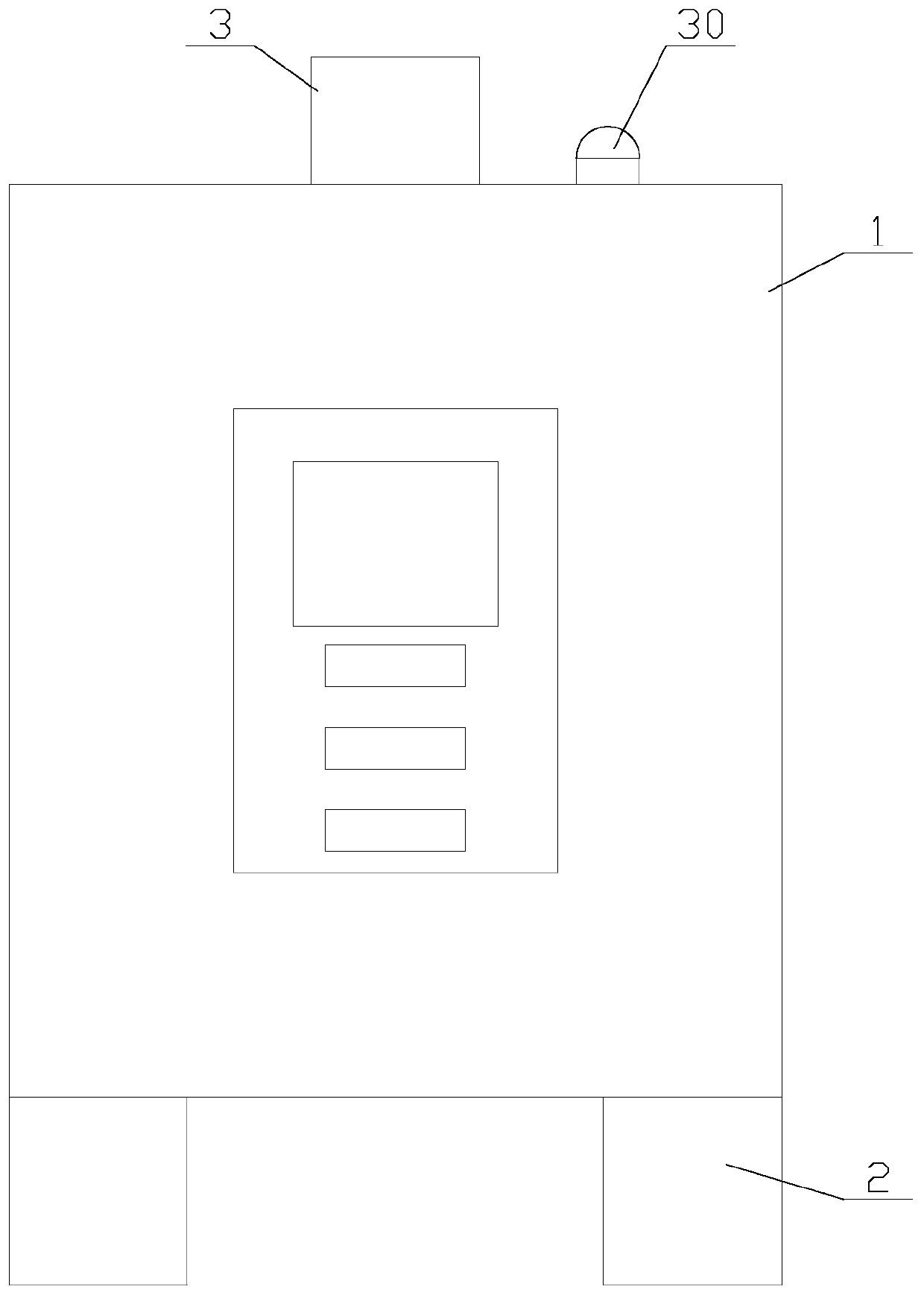
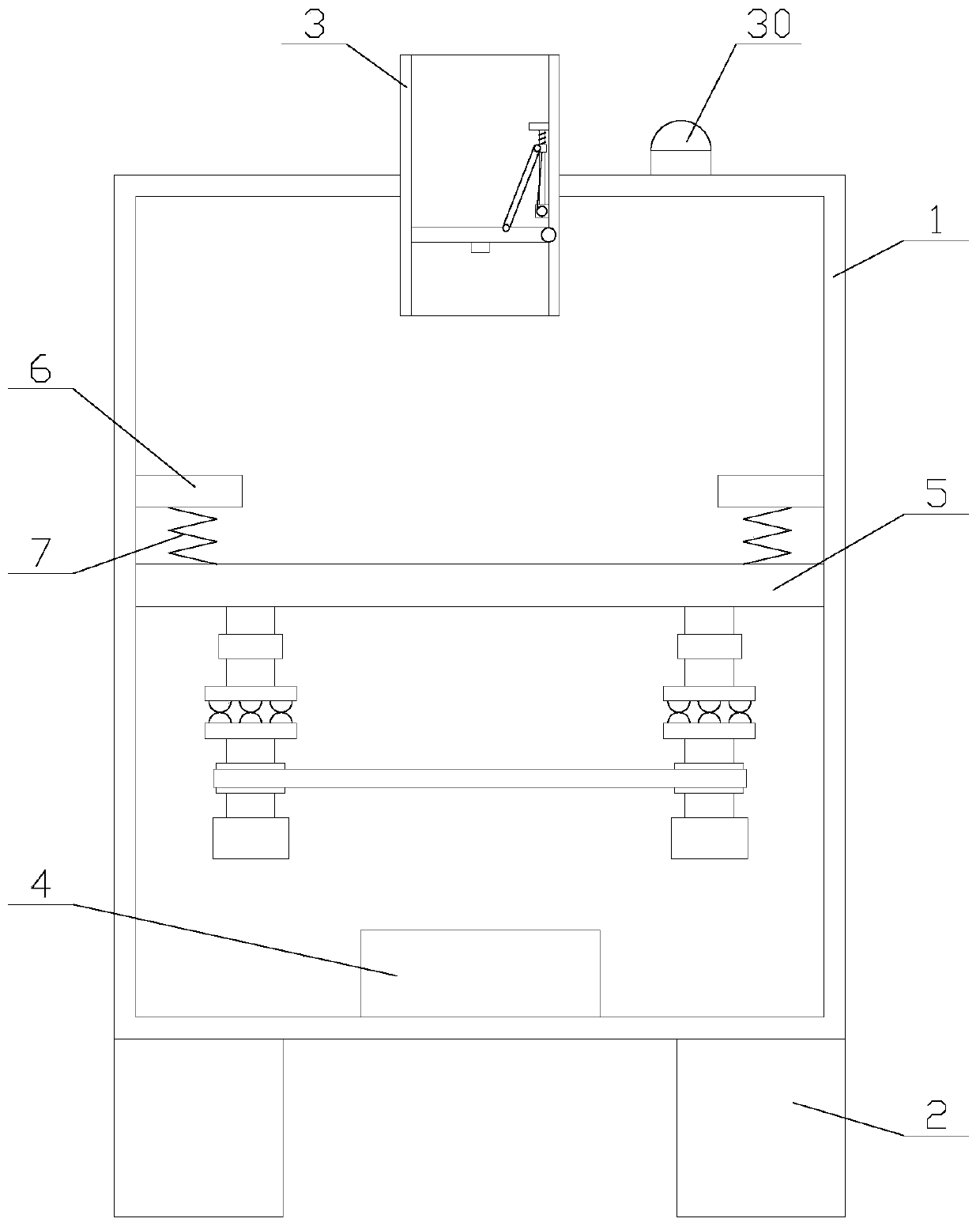
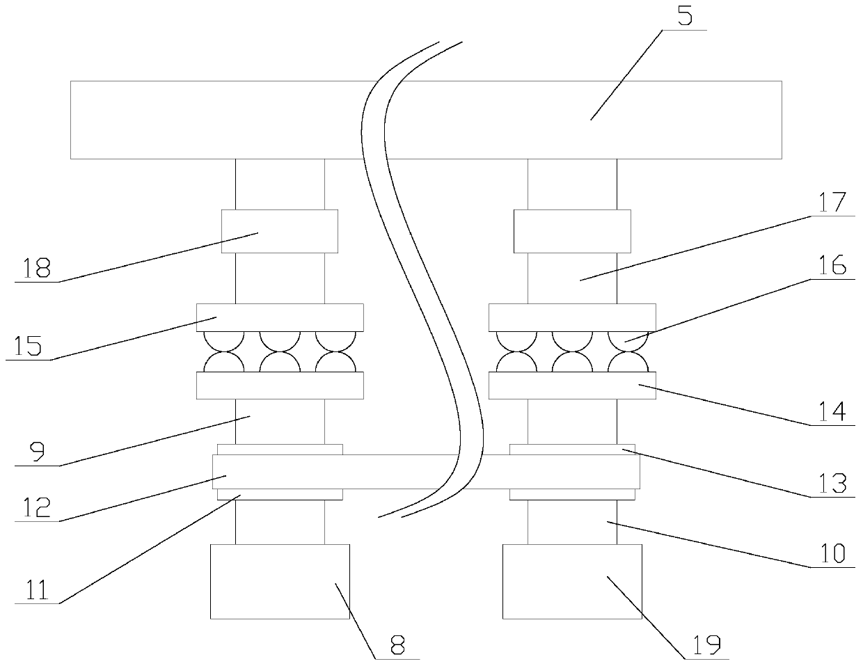
[0028] Such as figure 1 Shown, a kind of high-efficiency graphene production equipment with quantitative function comprises main body 1, placement table 5, microwave launcher 4 and four supports 2, and four supports 2 are fixed on the four corners of the bottom of main body 1 respectively, so The placement platform 5 and the microwave transmitter 4 are all arranged inside the main body 1, the placement platform 5 is arranged above the microwave transmitter 4, the main body 1 is provided with a PLC, and the microwave transmitter 4 is electrically connected to the PLC , the top of the main body 1 is provided with a feeding pipe 3, the feeding pipe 3 communicate...
PUM
 Abstract
Description
Claims
Application Information