
Production line for plastic back cover film coating

A production line and back cover technology, which is applied in the field of plastic back cover coating production line, can solve the problems of no circulation of equipment, manual transfer of brackets, metal and glass materials that cannot meet the use requirements, etc., to ensure stability and avoid manual handling. Effect

Pending Publication Date: 2019-05-21
张家港市铭斯特光电科技有限公司
View PDF7 Cites 1 Cited by
  • Summary
  • Abstract
  • Description
  • Claims
  • Application Information

AI Technical Summary

Problems solved by technology

[0002] The back cover of the mobile phone is the outer casing of the rear of the mobile phone, which is generally made of metal, glass and composite materials. Due to the poor texture of plastic materials, the use of metal materials and glass materials has become common in recent years. However, due to the advent of the 5G era, the fifth The signal frequency of the first-generation communication is completely different from that of the fourth-generation communication, and the requirements for materials are very high. Metal materials and glass materials cannot meet the requirements of use, so composite materials are widely used.
[0003] Due to the change from the hard material of metal and glass to the soft material of plastic, the existing production line cannot meet the needs of use. There are often problems with materials falling in the production line during the production process, which greatly affects production efficiency, and now There is equipment but no circulation, so that the brackets for fixing materials need to be manually transferred, which greatly affects production efficiency and is also prone to damage

Method used


Image

  • Production line for plastic back cover film coating
  • Production line for plastic back cover film coating
  • Production line for plastic back cover film coating

Examples


Embodiment Construction

[0026] The present invention will be further described below with reference to the accompanying drawings and specific embodiments, so that those skilled in the art can better understand and implement the present invention, but the examples cited are not intended to limit the present invention.

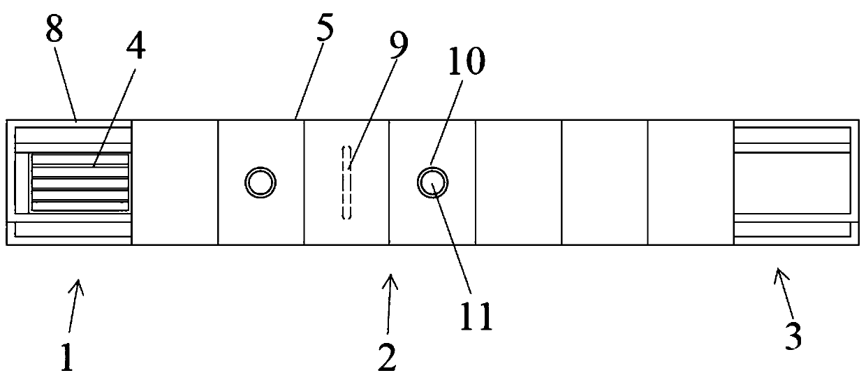
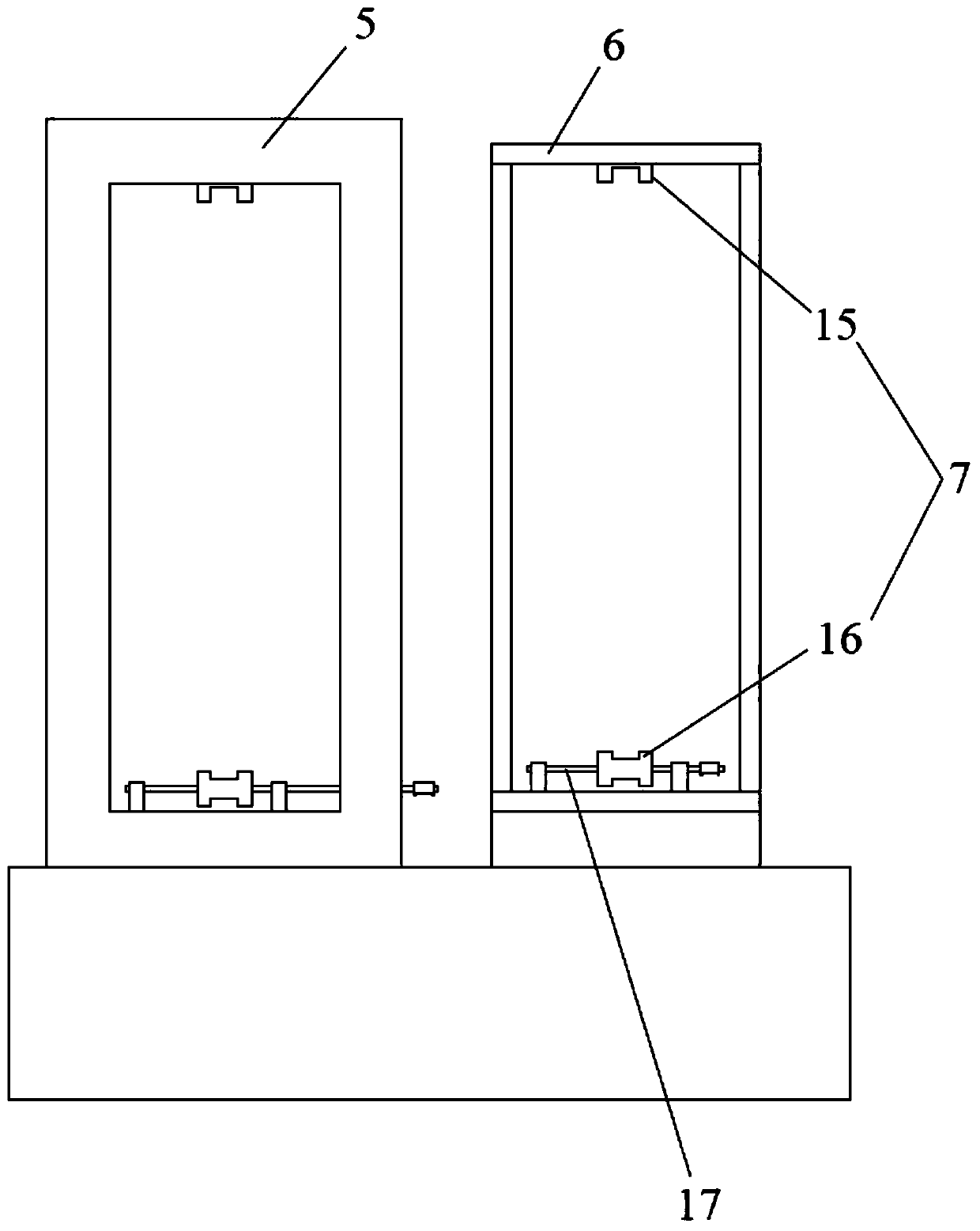
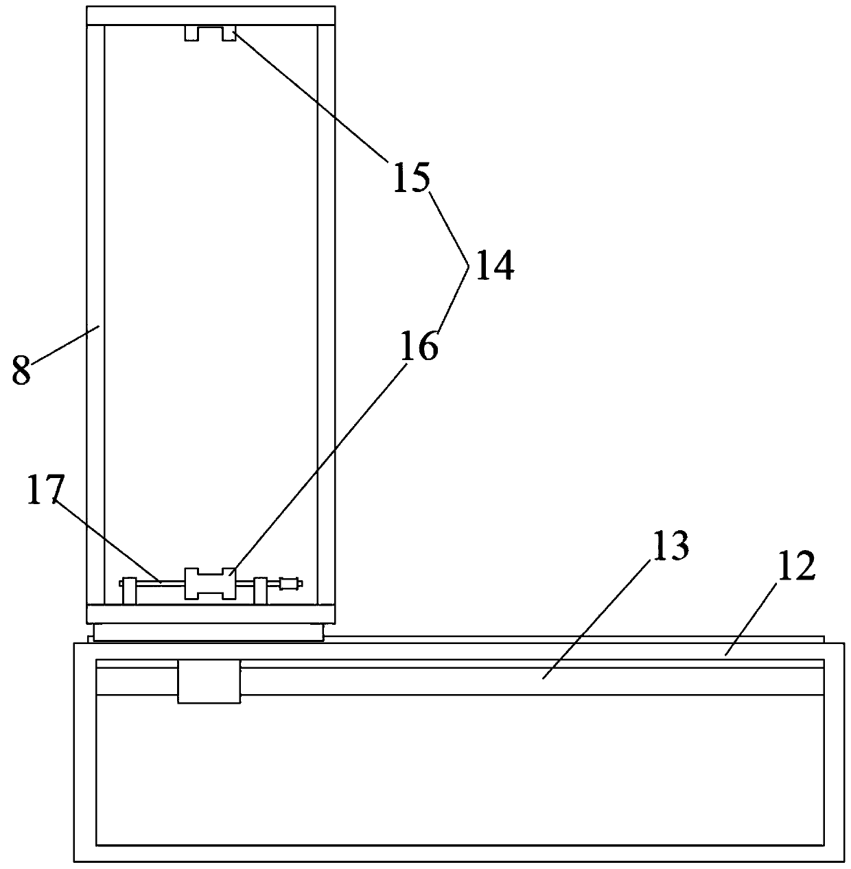
[0027] Reference Figure 1 to Figure 4 As shown, an embodiment of the production line for plastic back cover coating of the present invention includes a feeding zone 1, a coating zone 2, a discharging zone 3, and a moving frame 4. The coating zone is provided with a processing box 5 and a circulation rack 6, The processing box body and the circulation rack are both provided with a first transmission track 7, the processing box body and the circulation rack are arranged in parallel, and the loading area and the unloading area are provided with a transfer rack 8. The transfer rack will move the frame in the processing box and To move between the transfer racks, the transfer rack is arranged ...


PUM


Abstract

The invention discloses a production line for plastic back cover film coating. The production line comprises a feeding area, a film coating area, a discharging area and a movable frame. A treatment box and a circulating frame are arranged in the film coating area. First transmission rails are arranged in the treatment box and the circulating frame, the treatment box and the circulating frame are arranged in parallel, and transferring frames are arranged in the feeding area and the discharging area. The movable frame is moved between the treatment box and the circulating frames through the transferring frames. An ion source is arranged in the position, on one side of the feeding area, of the treatment box, a cold pump is arranged outside, the cold pump is connected with the interior of thetreatment box in a communicating manner, and a molecular pump is arranged on the cold pump. The transferring frames are arranged on a transferring base, and lead screw transmission assemblies are arranged between the transferring base and the transferring frames. Second transmission rails are arranged in the transferring frames. According to the production line, a low-temperature film coating process can be achieved, the yield of subsequent film coating can be guaranteed, a circulating function is achieved, and the production efficiency is improved.

Description

Technical field [0001] The invention relates to the technical field of surface treatment, in particular to a production line for coating a plastic back cover. Background technique [0002] The back cover of the mobile phone is the outer shell of the back of the mobile phone, which is generally made of metal, glass and composite materials. Due to the poor texture of plastic materials, the use of metal and glass materials has become common in recent years. However, due to the advent of the 5G era, the fifth The signal frequency of the next generation communication is completely different from that of the fourth generation, and the requirements for materials are very high. Metal materials and glass materials cannot meet the requirements of use, so composite materials are widely used. [0003] Due to the change from the hard material of metal and glass to the soft material of plastic, the existing production line cannot meet the needs of use, and the problem of materials falling in the...

Claims


Application Information

Patent Timeline
Patent Type & Authority Applications(China)
IPC IPC(8): C23C14/56C23C14/50
Inventor 朱杰
Owner 张家港市铭斯特光电科技有限公司
Learn More