Deposition system and gas transmission method thereof

A deposition system and gas transmission technology, which is applied in gaseous chemical plating, metal material coating process, coating, etc., can solve the problems of low utilization rate of the precursor body, large space occupation, high equipment cost, etc., and reduce the occupied space , reduce equipment costs, improve the effect of utilization

Active Publication Date: 2019-05-21
BEIJING NAURA MICROELECTRONICS EQUIP CO LTD
View PDF6 Cites 1 Cited by
  • Summary
  • Abstract
  • Description
  • Claims
  • Application Information

AI Technical Summary

Problems solved by technology

[0011] However, in the above-mentioned existing ALD device, the precursors A and B need to be alternately transported into the reaction chamber during transport, and there are only two transport paths, that is, in addition to entering the reaction chamber to participate in the reaction, in other steps Both will be transported to the factory exhaust gas treatment through the exhaust gas discharge device, so the precursor A source bottle and the precursor B sour

Method used


Image

  • Deposition system and gas transmission method thereof
  • Deposition system and gas transmission method thereof
  • Deposition system and gas transmission method thereof

Examples


Embodiment Construction

[0048] The specific embodiment of the present invention will be further described in detail below in conjunction with the accompanying drawings.

[0049] It should be noted that, in the following specific embodiments, when describing the embodiments of the present invention in detail, in order to clearly show the structure of the present invention for the convenience of description, the structures in the drawings are not drawn according to the general scale, and are drawn Partial magnification, deformation and simplification are included, therefore, it should be avoided to be interpreted as a limitation of the present invention.

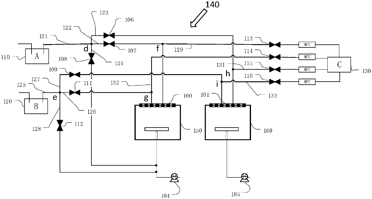
[0050] In the following specific embodiments of the present invention, please refer to figure 2 , figure 2 It is a schematic structural diagram of a deposition system in a preferred embodiment of the present invention. Such as figure 2 As shown, a deposition system of the present invention includes a first chamber 150 , a second chamber 160 and...


PUM


Abstract

The invention discloses a deposition system. The deposition system comprises a first cavity, a second cavity and a gas supply device shared by the first cavity and the second cavity. The gas supply device comprises a precursor source A, a precursor source B and a sweeping gas source C. The precursor source A is connected with the first cavity and the second cavity through a first cavity precursorA output pipeline and a second cavity precursor A output pipeline correspondingly. The precursor source B is connected with the first cavity and the second cavity through a first cavity precursor B output pipeline and a second cavity precursor B output pipeline correspondingly. The sweeping gas source C is connected with the first cavity through a first cavity precursor A sweeping pipeline and a first cavity precursor B sweeping pipeline and connected with the second cavity through a second cavity precursor A sweeping pipeline and a second cavity precursor B sweeping pipeline. The deposition system can increase the utilization rate of precursors, and the occupied space of the deposition system can be reduced. The invention further discloses a gas transmission method of the deposition system.

Description

technical field [0001] The present invention relates to the technical field of semiconductor equipment, and more specifically, to a deposition system and a gas transmission method thereof. Background technique [0002] Atomic layer deposition (ALD) is a technology that forms a deposited film by alternately feeding gas phase precursors into the reaction chamber and undergoing chemical reactions. This technology can deposit substances layer by layer in the form of a single atomic film. Plated on the surface of the substrate, when the precursors reach the surface of the deposition substrate, they will be chemically adsorbed on the surface of the substrate. The reaction chamber needs to be purged with an inert gas between precursor pulses to remove excess precursors that are not adsorbed on the substrate surface and ensure that chemical reactions only occur on the substrate surface. The ALD process is limited by its growth principle, its growth rate is the lowest compared with ...

Claims


Application Information

Patent Timeline
IPC IPC(8): C23C16/455
Inventor 纪红史小平李春雷赵雷超秦海丰张文强
Owner BEIJING NAURA MICROELECTRONICS EQUIP CO LTD
Why Eureka
Try Eureka