Existing-road-crossing cast-in-situ trough beam three-point sliding jacking construction method

A technology of jacking construction and trough beams, which is applied in bridges, bridge construction, erection/assembly of bridges, etc., can solve the problems of reducing the construction workload of temporary buttresses, and the deformation of the slideway beams on both sides is not synchronized.

Active Publication Date: 2019-05-21
CHINA RAILWAY FIRST GRP CO LTD +1
View PDF2 Cites 5 Cited by
  • Summary
  • Abstract
  • Description
  • Claims
  • Application Information

AI Technical Summary

Problems solved by technology

[0005] The technical problem to be solved by the present invention is to provide a three-point sliding and pushing construction method for cast-in-place channel beams spanning existing roads, which is reasonable in design, easy in construction and good in use effect , using two rear slideway beams and one front slideway beam to form a three-point longitudinal movement channel, and laying a horizontal beam at the bottom of the front and rear ends of the cast-in-place channel beam, which can effectively solve the problem of cast-in-place channel beams obliquely spanning existing roads There is a problem that the deformation of the slideway beams on both sides is not synchronized in the beam pushing construction, and only one temporary pier is constructed on each side of the existing road along the transverse bridge direction to support the front slideway beam, which can effectively reduce the number of temporary pier The amount of construction work can be reduced, and the cost can be effectively saved, and at the same time, it can effectively reduce or even avoid the impact on the use of existing roads

Method used


Image

  • Existing-road-crossing cast-in-situ trough beam three-point sliding jacking construction method
  • Existing-road-crossing cast-in-situ trough beam three-point sliding jacking construction method
  • Existing-road-crossing cast-in-situ trough beam three-point sliding jacking construction method

Examples


Embodiment Construction

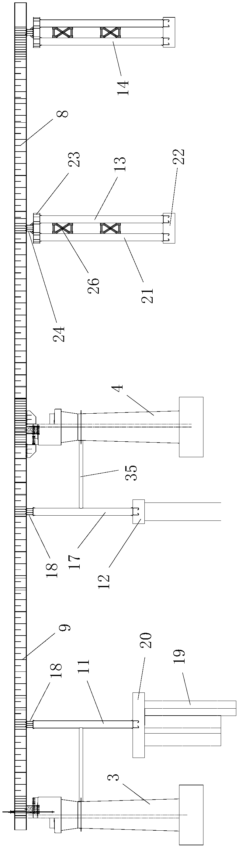
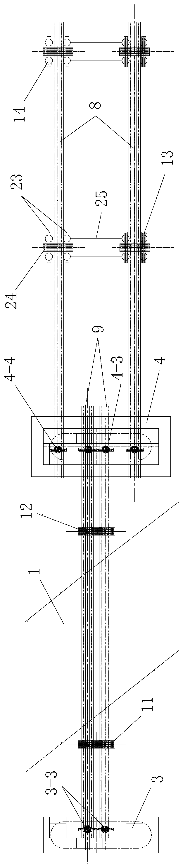
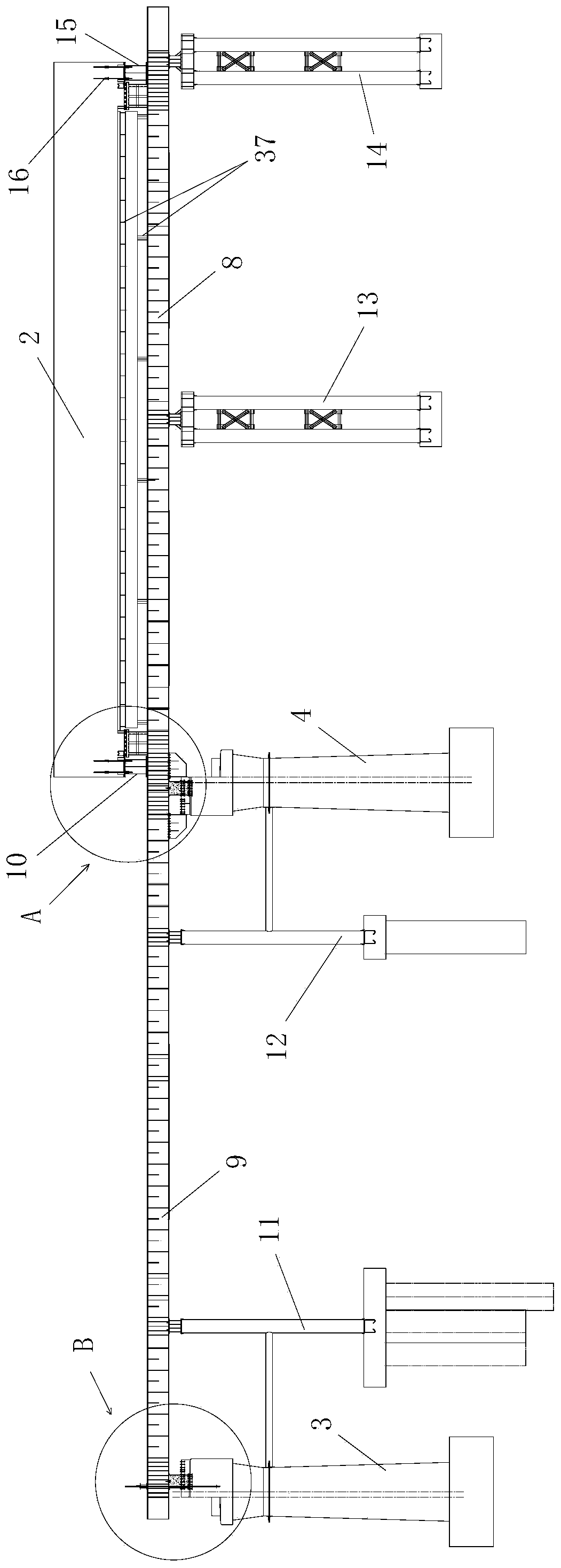
[0112] like Figure 21 A three-point sliding and jacking construction method for cast-in-place channel beams across existing roads is shown, combined with figure 1 , figure 2 , Figure 4 and Figure 5 , the pushed channel girder is a cast-in-place channel beam 2 erected between the front pier 3 and the rear pier 4 and is pushed by a pushing system. The cast-in-place channel beam 2 spans the existing road 1 The reinforced concrete beam has a concave cross section, the front end of the cast-in-place channel beam 2 is supported on the front pier 3 and the rear end is supported on the rear pier 4, and the cast-in-place channel beam 2 is horizontally arranged Straight beam and the angle between it and the existing road 1 is less than 90°;

[0113] combine figure 1 , figure 2 , image 3 , Figure 4 and Figure 5, the pushing system includes a traction device, four temporary buttresses arranged from front to back along the length direction of the pushed channel beam, two...


PUM


Abstract

The invention discloses an existing-road-crossing cast-in-situ trough beam three-point sliding jacking construction method. The method comprises steps of 1, pier and temporary pier construction; 2, slideway beam erection; 3, horizontal crossbeam layout; 4, trough beam cast-in-situ construction; 5, traction device installation; 6, jacking; 7, beam dropping. According to the method, design is reasonable, construction is easy, and the use effect is good; two back slide beams and one front slide beam are used for forming a three-point longitudinal passage, and horizontal cross beams are laid at the bottoms of the front end and the back end of the cast-in-situ trough beam respectively, the problem that deformation of the slide beams on the to sides is asynchronous in existing-road-oblique-crossing cast-in-situ trough beam jacking construction can be effectively solved; in addition, temporary piers are constructed on the two sides of an existing road in the cross bridge direction respectively, the temporary pier construction workload can be effectively reduced, and the cost can be effectively reduced; meanwhile, the influence on use of the existing road can be effectively reduced or evenavoided.

Description

technical field [0001] The invention belongs to the technical field of bridge construction, and in particular relates to a three-point sliding and pushing construction method of a cast-in-place channel beam spanning an existing road. Background technique [0002] The jacking method construction is to set up a prefabricated field behind the abutment along the bridge axis direction, and set up steel guide beams, temporary piers, slideways, horizontal jacks (also called jacking force devices or jacking force devices), etc., the actual During construction, after the beam body is processed in sections and longitudinally connected into a whole, the force is applied by a horizontal jack, and the beam is pushed forward section by section with the help of slideways and sliders, and the beam falls after it is in place. The jacking method construction is not only used for continuous girder bridges, but also for other bridge types (such as simply supported girder bridges). It can also b...

Claims


Application Information

Patent Timeline
Patent Type & Authority Applications(China)
IPC IPC(8): E01D21/00
Inventor 何占忠牛谋张全利罗伟杨军锋尚照辉王永平杨俊超焦可心魏亮高志宇郝洪波王海洋王文龙
Owner CHINA RAILWAY FIRST GRP CO LTD
Why Eureka
Try Eureka