
Fan impeller of air conditioner and manufacturing technology thereof

An air-conditioning fan and impeller technology, which is applied in the direction of mechanical equipment, machines/engines, liquid fuel engines, etc., can solve the problems of low connection strength, easy damage, complex process, etc., to improve production efficiency, enhance connection strength, and uncomplicated process Effect

Active Publication Date: 2019-05-21
四川贝特风机有限公司
View PDF12 Cites 0 Cited by
  • Summary
  • Abstract
  • Description
  • Claims
  • Application Information

AI Technical Summary

Problems solved by technology

[0005] The purpose of the present invention is to provide an air conditioner fan impeller to solve the problems in the prior art that the impeller blades are thinner, have low connection strength, are easily damaged, have high requirements for solder in processing, high manufacturing cost and complicated process , the present invention also provides the manufacturing process of manufacturing this air conditioner fan impeller

Method used


Image

  • Fan impeller of air conditioner and manufacturing technology thereof
  • Fan impeller of air conditioner and manufacturing technology thereof
  • Fan impeller of air conditioner and manufacturing technology thereof

Examples


Embodiment 1

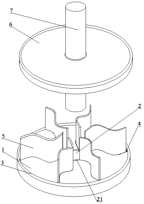
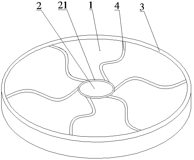
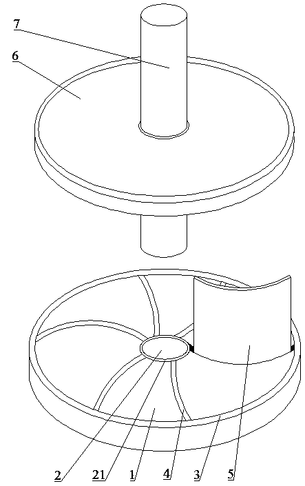
[0032] Such as figure 1 , image 3 As shown, the air conditioner fan impeller provided by the present invention includes: a fixed chassis 1, a shaft hole 2 arranged at the center of the fixed chassis 1, an outer flange 3 arranged at the edge of the fixed chassis 1, and several strips arranged on the upper surface of the fixed chassis 1. The mounting groove 4, several blades 5 engaged in the mounting groove 4, the upper cover 6 arranged symmetrically with the fixed chassis 1; the edge of the central axis hole 2 is provided with an inner flange 21; to the inner flange 21, and the other end is connected to the outer flange 3; the mounting grooves 4 are circularly arranged on the upper surface of the fixed chassis 1; the thickness of the blades 5 is smaller than the width of the mounting grooves 4; the blades 5 and the installation groove 4 are provided with metal injected and cooled by casting; the upper cover is connected with the fixed chassis 1 through the rotating shaft 7 be...

Embodiment 2

[0037] On the basis of Embodiment 1, the shape of the blade 5 preferably adopted in this embodiment is a C-shaped blade, and the C-shaped blade is relative to the generally used straight blade. A vortex airflow can be formed, so that the airflow can be transported at high speed and efficiently, and the connection method between the blade and the fixed chassis described in the present invention can be suitable for the installation of the C-shaped blade.

Embodiment 3

[0039] On the basis of embodiment 1, the material of blade 5 described in the present invention is titanium alloy, and titanium alloy metal is the relatively light metal of relative mass, and in the working operation of impeller, has reduced the load of impeller, has improved mechanical efficiency.


PUM


Abstract

The invention discloses a fan impeller of an air conditioner. The fan impeller of the air conditioner comprises a fixing chassis, a shaft hole which is formed in the center of the fixing chassis, an outer convex ring which is arranged at the side edge of the fixing chassis, a plurality of mounting grooves which are formed in the upper surface of the fixing chassis, a plurality of blades which areclamped into the mounting grooves, and an upper cover which is symmetric with the fixing chassis, wherein an inner convex ring is arranged at the side edge of the central shaft hole; one end of each mounting groove is connected to the inner convex ring, and the other end of each mounting groove is connected to the outer convex ring; the mounting grooves are arranged on the upper surface of the fixing chassis in a circle form; and cooled metal is poured between the blades and the mounting grooves. With the adoption of the fan impeller, the problem that blades are easily broken in traditional welding or other connecting manners is avoided; and the connecting strength of the blades and the fixing chassis is improved. The invention also provides a manufacturing technology of the fan impeller.The technology is applicable to manufacturing of fan impellers with different size and different blade thickness; the manufacturing cost is low; and the production efficiency is high.

Description

technical field [0001] The invention relates to the technical field of fan manufacturing, in particular to an air-conditioning fan impeller and a manufacturing process thereof. Background technique [0002] The fan is a mechanical device that converts mechanical energy into gas energy through rotating blades. The air-conditioning fan is one of the fans. It has the characteristics of compact structure, large air volume, high firmware integration, and low noise. The impeller is an air-conditioning fan. Its geometry, size, number of blades and manufacturing precision have a great influence on performance. The impeller is corrected by static balance or dynamic balance to ensure the smooth rotation of the fan. According to the direction of the blade outlet, the impeller is divided into three types: forward, radial and backward. The top of the blade of the forward impeller is inclined to the direction of impeller rotation; the top of the blade of the radial impeller is radial, a...

Claims


Application Information

Patent Timeline
IPC IPC(8): F04D29/28F04D29/30F04D29/02B23P15/04B22D19/04
Inventor 冯海亮
Owner 四川贝特风机有限公司
Learn More