
A pipe crawling robot and its crawling method

A crawling robot and robot technology, applied in the field of bionic robots, can solve the problems of large energy loss, limited traction force, complex structure and other problems in the movement mode, and achieve the effect of simple structure, low cost and low energy loss

Active Publication Date: 2020-07-10
HOHAI UNIV CHANGZHOU
View PDF6 Cites 0 Cited by
  • Summary
  • Abstract
  • Description
  • Claims
  • Application Information

AI Technical Summary

Problems solved by technology

[0005] The Chinese invention patent with the publication number CN107842666A discloses a caterpillar-like peristaltic pipe crawling robot and its control method. The torque of the motor is transmitted to the screw, so that the slider of the screw nut moves along the direction of the screw. Through the scissors mechanism, the lever principle has the characteristics of large clamping force and forward contraction during clamping, so as to realize the grip outside the tube. Clamping and support in the pipe; the displacement module makes the clamping module rotate flexibly in the plane through the combined movement of the two cylinders with different elongation distances and the motor-driven active connecting plate rotation; then through the alternate clamping movement and telescopic movement of the two claws The reciprocating linear motion of the joint electric cylinder makes the robot crawl along the pipeline; the application has two working modes of crawling inside the pipe and crawling outside the pipe; however, its structure is relatively complicated and the cost is high; and its displacement module is driven by pneumatics, The traction is limited, the energy consumption of the movement mode is large, and it is not suitable for crawling in curved pipes

Method used


Image

  • A pipe crawling robot and its crawling method
  • A pipe crawling robot and its crawling method
  • A pipe crawling robot and its crawling method

Examples


Embodiment 1

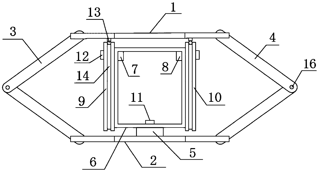
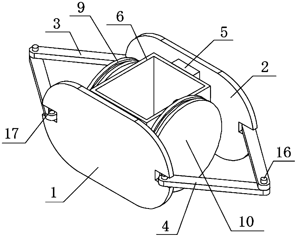
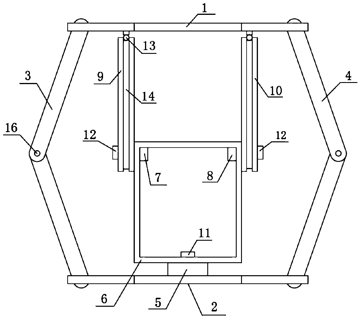
[0040] Such as Figures 1 to 3 As shown, this embodiment discloses a pipeline crawling robot, which includes four telescopic mechanisms with the same structure and connected end to end in sequence, namely the first telescopic mechanism 100, the second telescopic mechanism 200, the third telescopic mechanism 300 and the fourth telescopic mechanism. Mechanism 400; the telescopic mechanism includes: an upper support plate 1, a lower support plate 2, a first support link 3, a second support link 4, a support platform 5, a box body 6, a first motor 7, and a second motor 8 1. The first eccentric wheel 9 and the second eccentric wheel 10; the upper support plate 1 of the first telescopic mechanism 100 is provided with a detection unit for detecting internal obstacles or bends in the pipeline;

[0041] The upper support plate 1 and the lower support plate 2 are movably connected through the first support link 3 and the second support link 4; the support platform 5 is arranged on the l...

Embodiment 2

[0051] Such as Image 6 As shown, this embodiment provides a crawling method for a pipeline crawling robot in a vertical pipeline, which specifically includes the following steps:

[0052] S11, the robot is in the initial crawling state, the first telescopic mechanism 100 and the second telescopic mechanism 200 of the robot are in a retracted state, and the third telescopic mechanism 300 and the fourth telescopic mechanism 400 of the robot are in a stretched state; through the first telescopic mechanism 100 and The supporting link of the second telescoping mechanism 200 is against the pipe to provide friction and prevent the robot from falling;

[0053] S12, the first telescopic mechanism 100 of the robot is converted into a stretched state, and at the same time, the third telescopic mechanism 300 is converted into a contracted state, pulling the fourth telescopic mechanism 400 to move upward; supported by the second telescopic mechanism 200 and the third telescopic mechanism ...

Embodiment 3

[0060] Such as Figure 5 , 7 As shown, this embodiment provides a method for a pipeline crawling robot to crawl on a curve, which specifically includes the following steps:

[0061] S21, when the detection unit on the first telescopic mechanism 100 detects a curve, the second telescopic mechanism 200, the third telescopic mechanism 300, and the fourth telescopic mechanism 400 are in the retracted state, and the control module in the first telescopic mechanism 100 controls the second The first motor 7 and the second motor 8 implement differential control, so that the first telescopic mechanism 100 stretches at a small angle near the first support link 3 on the inside of the curve, and stretches at a large angle near the second support link 4 on the outside of the curve , so that the first telescopic mechanism 100 of the robot enters the curve;

[0062] S22, the control module in the second telescopic mechanism 200 of the robot performs differential control on the first motor ...


PUM


Abstract

The invention discloses a pipeline crawling robot and a crawling method thereof. The pipeline crawling robot comprises four telescopic mechanisms which are the same in structure and are connected endto end in sequence. Each telescopic mechanism comprises an upper supporting plate, a lower supporting plate, a first supporting connecting rod, a second supporting connecting rod, a supporting platform, a box body, a first motor, a second motor, a first eccentric wheel and a second eccentric wheel. According to the pipeline crawling robot and the crawling method thereof, a control module is used for synchronously having control over the two corresponding motors so as to drive the corresponding telescopic mechanism to contract or stretch, and because of mutual cooperation of the telescopic mechanisms, the pipeline crawling robot can crawl in a pipeline; and when the control module is used for having differential motion on the two corresponding motors so as to the two eccentric wheels of thecorresponding telescopic mechanism to rotate at different angles, and the telescopic mechanism can turn towards the turning direction of the pipeline. The pipeline crawling robot can be applicable tothe complex internal environment of the pipeline, and can carry out job tasks such as pipeline detection, maintenance and cleaning efficiently instead of human.

Description

technical field [0001] The invention belongs to the technical field of bionic robots, in particular to a pipeline crawling robot and a crawling method thereof. Background technique [0002] As one of the five major transportation methods in the world, oil and gas transportation plays an important role in the national economy, and pipeline transportation of oil and natural gas has a wide range of applications. Once the pipelines transporting oil and gas are damaged and leaked, huge losses will be caused. Pipelines are generally buried deep underground, on the seabed or in buildings, which brings great inconvenience to manual maintenance. The traditional way of overhauling the pipeline excavation will cause damage to the pipeline and waste of manpower. Therefore, the detection of pipelines has always been a concern of various countries. [0003] Nowadays, with the improvement of information technology and control technology, robot technology has been greatly developed. Rob...

Claims


Application Information

Patent Timeline
Patent Type & Authority Patents(China)
IPC IPC(8): F16L55/28F16L101/12F16L101/30
Inventor 周建华李向国
Owner HOHAI UNIV CHANGZHOU
Learn More