
Asynchronous motor excitation mutual inductance curve measuring system and measuring method

A technology of asynchronous motor and measurement method, which is applied in the direction of motor generator testing, etc., can solve the problems of inability to achieve accurate orientation of rotor magnetic field, inability to obtain excitation mutual inductance curve, and reduced system efficiency, so as to improve the accuracy of rotor magnetic field orientation and real-time compensation Rotor time constant, effect of simple system design

Active Publication Date: 2019-05-21
CRRC QINGDAO SIFANG ROLLING STOCK RES INST
View PDF11 Cites 5 Cited by
  • Summary
  • Abstract
  • Description
  • Claims
  • Application Information

AI Technical Summary

Problems solved by technology

[0003] The conventional excitation mutual inductance identification method can only measure the excitation mutual inductance value under a specific motor operating state, but cannot obtain the excitation mutual inductance curve
In the actual control process of the asynchronous motor, if there is a deviation in the excitation mutual inductance parameters, the asynchronous motor will run under excitation or over excitation, and the accurate orientation of the rotor magnetic field cannot be achieved, resulting in poor dynamic and static performance of the motor, such as increased motor loss and system efficiency. Problems such as reduction, torque ripple, torque accuracy deterioration, system speed regulation performance deterioration, field weakening control performance deterioration, etc.

Method used


Image

  • Asynchronous motor excitation mutual inductance curve measuring system and measuring method
  • Asynchronous motor excitation mutual inductance curve measuring system and measuring method
  • Asynchronous motor excitation mutual inductance curve measuring system and measuring method

Examples


Embodiment

[0078] In order to highlight the advantages of this algorithm, take the excitation mutual inductance curve of a 25kW three-phase asynchronous motor for a certain type of electric vehicle as an example, the excitation mutual inductance curve refers to image 3 shown. In this embodiment, different excitation current reference values ​​are set through the host computer, the torque current reference value is equal to the excitation current reference value, a measurement point of 5A is set, and then the slip angle frequency is modified in real time using the host computer. When the motor output torque is maximum , record the torque value. Finally, the excitation mutual inductance value at different excitation currents is calculated by the excitation mutual inductance measurement formula (1), and the relationship curve between the excitation mutual inductance and the excitation current is obtained, that is, the excitation mutual inductance curve. The excitation mutual inductance cu...


PUM


Abstract

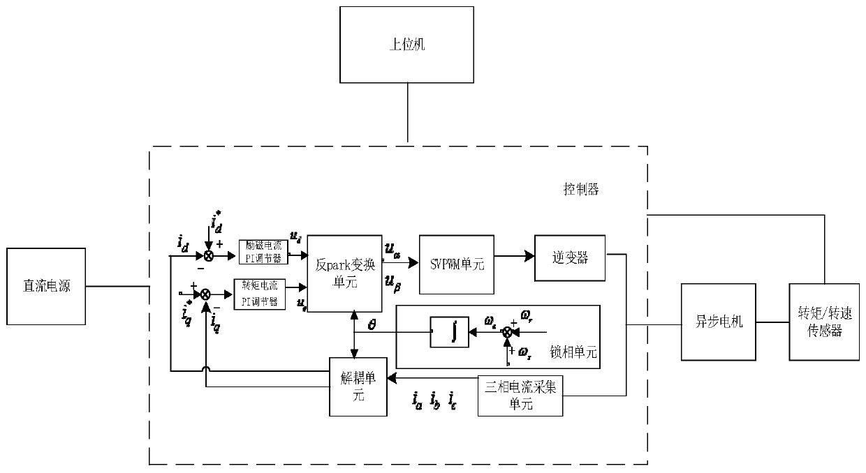
The invention relates to an asynchronous motor excitation mutual inductance curve measuring system and a measuring method. The system comprises a controller, a three-phase asynchronous motor, a sensing unit and an upper computer. The sensing unit measures an output torque and rotor angular frequency information in real time and sends to the controller. The controller is connected with the sensingunit, the three-phase asynchronous motor and the upper computer so as to control the work of a motor. The upper computer sets different excitation current reference values, a slip angle frequency is adjusted in real time so that a rotor magnetic field is accurately oriented, the maximums of the motor output torques corresponding to different excitation current reference values are recorded, and the excitation mutual inductance values corresponding to different excitation current reference values are solved to acquire an excitation mutual inductance curve. By using the measuring method, the excitation mutual inductance curve of the motor can be measured quickly and accurately. Excitation mutual inductance curve data can be used as a look-up table used for a rotor magnetic field oriented vector control algorithm, which significantly improves rotor magnetic field orientation accuracy, torque control accuracy and weak magnetic control stability.

Description

technical field [0001] The invention belongs to the technical field of motor-to-drag testing, and in particular relates to an asynchronous motor excitation mutual inductance curve measurement system and a measurement method thereof. Background technique [0002] The vector control of three-phase asynchronous motors based on rotor field orientation is widely used in the field of AC transmission. This method decomposes the stator current into excitation current components and torque current components, and decouples the excitation control and torque control, so that the asynchronous motor has Control performance comparable to DC motors. Indirect field orientation is a commonly used field orientation scheme in engineering practice. The rotor flux orientation angle is obtained by integrating the electrical angular frequency, where the electrical angular frequency is the sum of the rotor angular frequency and the slip angular frequency. Accurate field orientation depends on accu...

Claims


Application Information

Patent Timeline
Patent Type & Authority Applications(China)
IPC IPC(8): G01R31/34
Inventor 赵许强杨东军林显琦胡冰崔晓光咸粤飞
Owner CRRC QINGDAO SIFANG ROLLING STOCK RES INST
Learn More